Difference between revisions of "User:NKArranz"
| Line 7: | Line 7: | ||
Spring 2017 - Digital Craft Q8 | Spring 2017 - Digital Craft Q8 | ||
| + | –––––––––––––––––––––––––––––––––––––––––––––––––––––––––––––––––––––––––––––––––––––––––––––––––––––––––––––––––––––––––––––––––––––––––––––––––––––––––––––––––––––––– | ||
| − | + | '''First Group Project: Demonstrate a Concept''' | |
| − | |||
| − | + | –––––––––––––––––––––––––––––––––––––––––––––––––––––––––––––––––––––––––––––––––––––––––––––––––––––––––––––––––––––––––––––––––––––––––––––––––––––––––––––––––––––––– | |
[[File:DigitalCraft_NMASS_Project1(s).pdf |left|alt text]] | [[File:DigitalCraft_NMASS_Project1(s).pdf |left|alt text]] | ||
| − | |||
| + | –––––––––––––––––––––––––––––––––––––––––––––––––––––––––––––––––––––––––––––––––––––––––––––––––––––––––––––––––––––––––––––––––––––––––––––––––––––––––––––––––––––––– | ||
'''Second Group Project: Measuring Voltage and Current''' | '''Second Group Project: Measuring Voltage and Current''' | ||
| + | |||
| + | –––––––––––––––––––––––––––––––––––––––––––––––––––––––––––––––––––––––––––––––––––––––––––––––––––––––––––––––––––––––––––––––––––––––––––––––––––––––––––––––––––––––– | ||
[[File:NKArranz_Project2_01Setup.JPG |300px|left|Setup]] | [[File:NKArranz_Project2_01Setup.JPG |300px|left|Setup]] | ||
| Line 34: | Line 36: | ||
'''Current:''' 13.8 mA | '''Current:''' 13.8 mA | ||
| + | –––––––––––––––––––––––––––––––––––––––––––––––––––––––––––––––––––––––––––––––––––––––––––––––––––––––––––––––––––––––––––––––––––––––––––––––––––––––––––––––––––––––– | ||
[[File:NKArranz_Project2_04Resistance.JPG |200px|left|Resistance]] | [[File:NKArranz_Project2_04Resistance.JPG |200px|left|Resistance]] | ||
| Line 54: | Line 57: | ||
6 mA | 6 mA | ||
| + | –––––––––––––––––––––––––––––––––––––––––––––––––––––––––––––––––––––––––––––––––––––––––––––––––––––––––––––––––––––––––––––––––––––––––––––––––––––––––––––––––––––––– | ||
[[File:NKArranz_Project2_09RC2.JPG |200px|left|ResistorsinParallel]] | [[File:NKArranz_Project2_09RC2.JPG |200px|left|ResistorsinParallel]] | ||
| − | |||
| − | |||
| − | |||
| − | |||
| Line 70: | Line 70: | ||
| − | + | –––––––––––––––––––––––––––––––––––––––––––––––––––––––––––––––––––––––––––––––––––––––––––––––––––––––––––––––––––––––––––––––––––––––––––––––––––––––––––––––––––––––– | |
| − | |||
| − | |||
| − | |||
| − | |||
| − | |||
| − | |||
| − | |||
| − | |||
| − | |||
| − | |||
| − | |||
| − | |||
| − | |||
| − | |||
| − | |||
| − | |||
| − | |||
| − | |||
| − | |||
| − | |||
'''Third Project: Creating a Sound Circuit''' | '''Third Project: Creating a Sound Circuit''' | ||
| + | –––––––––––––––––––––––––––––––––––––––––––––––––––––––––––––––––––––––––––––––––––––––––––––––––––––––––––––––––––––––––––––––––––––––––––––––––––––––––––––––––––––––– | ||
[[File:NKArranz_DCP3_01-Parts.JPG |300px|left|Components]] | [[File:NKArranz_DCP3_01-Parts.JPG |300px|left|Components]] | ||
| Line 104: | Line 85: | ||
After reading the schematic, the necessary components were gathered. Unfortunately for me there were no 100K left to complete my circuit, so I improvised. I at first considered using a combination of a 15K and 82K resistors, but in the end I just used 120K resistors. I also redrew the schematic to make a more realistic representation of the terminals of the 555 timer. | After reading the schematic, the necessary components were gathered. Unfortunately for me there were no 100K left to complete my circuit, so I improvised. I at first considered using a combination of a 15K and 82K resistors, but in the end I just used 120K resistors. I also redrew the schematic to make a more realistic representation of the terminals of the 555 timer. | ||
| + | –––––––––––––––––––––––––––––––––––––––––––––––––––––––––––––––––––––––––––––––––––––––––––––––––––––––––––––––––––––––––––––––––––––––––––––––––––––––––––––––––––––––– | ||
[[File:NKArranz_DCP3_04-Layout.JPG |300px|left|Components]] | [[File:NKArranz_DCP3_04-Layout.JPG |300px|left|Components]] | ||
| Line 109: | Line 91: | ||
After receiving a copper plate, I made an outline of where I wanted to manually etch the circuit paths. | After receiving a copper plate, I made an outline of where I wanted to manually etch the circuit paths. | ||
| + | –––––––––––––––––––––––––––––––––––––––––––––––––––––––––––––––––––––––––––––––––––––––––––––––––––––––––––––––––––––––––––––––––––––––––––––––––––––––––––––––––––––––– | ||
[[File:NKArranz_DCP3_05-ManuelEtching.JPG |300px|left|Components]] | [[File:NKArranz_DCP3_05-ManuelEtching.JPG |300px|left|Components]] | ||
| − | |||
Due to the dremel at the Interaction Station repeatedly losing power, I went to the woodshop and used a drill to etch the rest of the plate. | Due to the dremel at the Interaction Station repeatedly losing power, I went to the woodshop and used a drill to etch the rest of the plate. | ||
| + | –––––––––––––––––––––––––––––––––––––––––––––––––––––––––––––––––––––––––––––––––––––––––––––––––––––––––––––––––––––––––––––––––––––––––––––––––––––––––––––––––––––––– | ||
[[File:NKArranz_DCP3_06-Soldering.JPG |300px|left|Components]] | [[File:NKArranz_DCP3_06-Soldering.JPG |300px|left|Components]] | ||
| − | |||
Soldering with the original 555 timer provide to be quite difficult, so I replaced it with a larger 555 timer that was easier to handle. | Soldering with the original 555 timer provide to be quite difficult, so I replaced it with a larger 555 timer that was easier to handle. | ||
| + | –––––––––––––––––––––––––––––––––––––––––––––––––––––––––––––––––––––––––––––––––––––––––––––––––––––––––––––––––––––––––––––––––––––––––––––––––––––––––––––––––––––––– | ||
[[File:NKArranz_DCP3_07-Testing.JPG |300px|left|Components]] | [[File:NKArranz_DCP3_07-Testing.JPG |300px|left|Components]] | ||
[[File:NKArranz_DCP3_08-Final.JPG |300px|middle|Components]] | [[File:NKArranz_DCP3_08-Final.JPG |300px|middle|Components]] | ||
| − | |||
Final circuit - completely operational. | Final circuit - completely operational. | ||
Revision as of 07:25, 27 May 2017
Hello!
My name is Niko Arranz and I'm an exchanged student from Boston, US.
My email is NKArranz@massart.edu.
Spring 2017 - Digital Craft Q8
––––––––––––––––––––––––––––––––––––––––––––––––––––––––––––––––––––––––––––––––––––––––––––––––––––––––––––––––––––––––––––––––––––––––––––––––––––––––––––––––––––––––
First Group Project: Demonstrate a Concept
––––––––––––––––––––––––––––––––––––––––––––––––––––––––––––––––––––––––––––––––––––––––––––––––––––––––––––––––––––––––––––––––––––––––––––––––––––––––––––––––––––––––
File:DigitalCraft NMASS Project1(s).pdf
––––––––––––––––––––––––––––––––––––––––––––––––––––––––––––––––––––––––––––––––––––––––––––––––––––––––––––––––––––––––––––––––––––––––––––––––––––––––––––––––––––––––
Second Group Project: Measuring Voltage and Current
––––––––––––––––––––––––––––––––––––––––––––––––––––––––––––––––––––––––––––––––––––––––––––––––––––––––––––––––––––––––––––––––––––––––––––––––––––––––––––––––––––––––
Original Readings:
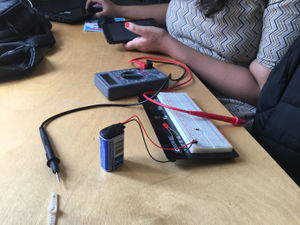
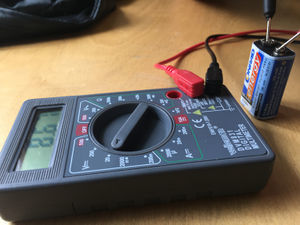
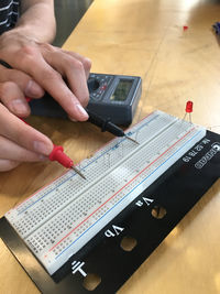
Battery: 8.67V Resistance: 470 ohms Current: 13.8 mA
––––––––––––––––––––––––––––––––––––––––––––––––––––––––––––––––––––––––––––––––––––––––––––––––––––––––––––––––––––––––––––––––––––––––––––––––––––––––––––––––––––––––
Readings with Resistors in Series:
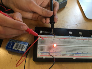
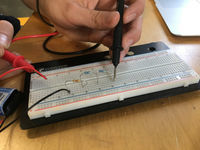
Volts in series: 9.3 V 6.2 V 3.1 V Resistance in series: 470 ohms - 1 series 940 ohms - 2 series 1399 ohms - 3 series Current in series: 18 mA 9 mA 6 mA
––––––––––––––––––––––––––––––––––––––––––––––––––––––––––––––––––––––––––––––––––––––––––––––––––––––––––––––––––––––––––––––––––––––––––––––––––––––––––––––––––––––––
Readings with Resistors in Parallel:
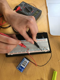
Volts in parallel: 5.93 V Resistance in parallel: 235 ohms - 2 parallel 156.66 ohms - 3 parallel Current in parallel: 47 mA
––––––––––––––––––––––––––––––––––––––––––––––––––––––––––––––––––––––––––––––––––––––––––––––––––––––––––––––––––––––––––––––––––––––––––––––––––––––––––––––––––––––––
Third Project: Creating a Sound Circuit
––––––––––––––––––––––––––––––––––––––––––––––––––––––––––––––––––––––––––––––––––––––––––––––––––––––––––––––––––––––––––––––––––––––––––––––––––––––––––––––––––––––––
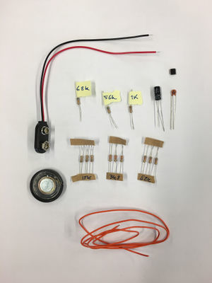
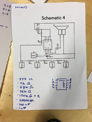
After reading the schematic, the necessary components were gathered. Unfortunately for me there were no 100K left to complete my circuit, so I improvised. I at first considered using a combination of a 15K and 82K resistors, but in the end I just used 120K resistors. I also redrew the schematic to make a more realistic representation of the terminals of the 555 timer.
––––––––––––––––––––––––––––––––––––––––––––––––––––––––––––––––––––––––––––––––––––––––––––––––––––––––––––––––––––––––––––––––––––––––––––––––––––––––––––––––––––––––
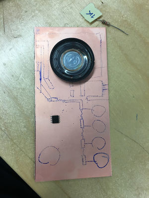
After receiving a copper plate, I made an outline of where I wanted to manually etch the circuit paths.
––––––––––––––––––––––––––––––––––––––––––––––––––––––––––––––––––––––––––––––––––––––––––––––––––––––––––––––––––––––––––––––––––––––––––––––––––––––––––––––––––––––––
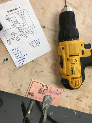
Due to the dremel at the Interaction Station repeatedly losing power, I went to the woodshop and used a drill to etch the rest of the plate.
––––––––––––––––––––––––––––––––––––––––––––––––––––––––––––––––––––––––––––––––––––––––––––––––––––––––––––––––––––––––––––––––––––––––––––––––––––––––––––––––––––––––
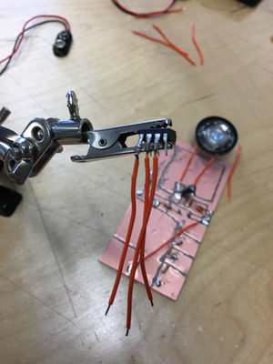
Soldering with the original 555 timer provide to be quite difficult, so I replaced it with a larger 555 timer that was easier to handle.
––––––––––––––––––––––––––––––––––––––––––––––––––––––––––––––––––––––––––––––––––––––––––––––––––––––––––––––––––––––––––––––––––––––––––––––––––––––––––––––––––––––––
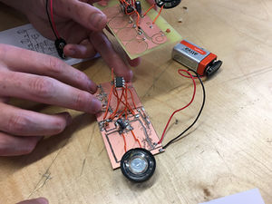
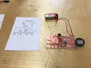
Final circuit - completely operational.
