Difference between revisions of "User:Sneha Arvind"
Sneha Arvind (talk | contribs) (adding video link) |
Sneha Arvind (talk | contribs) |
||
| Line 53: | Line 53: | ||
The sound produced by the board was different. The gradation in sound was absent. The sound produced would play if you place your finger on the touchpad and would pause if any of the other touch pads on the circuit were touched. The outcome was 'reversed'. | The sound produced by the board was different. The gradation in sound was absent. The sound produced would play if you place your finger on the touchpad and would pause if any of the other touch pads on the circuit were touched. The outcome was 'reversed'. | ||
| − | + | I tried uploading a video of it didn't work. To see a video of my circuit, please visit my Youtube Channel 'Sneha Arvind'. Thanks! | |
| + | |||
| + | ==Personal Project== | ||
Revision as of 20:26, 21 June 2017
Hello! Welcome to my page!
Name : Sneha Arvind Email : 0941442@hr.nl
Department - Spatial Design \ Q8

Group Exercise
Group Members - Sneha Arvind Shipra Balasubramani Mirdu Jhangiani Niko Arranz Aayushi Katare
In this exercise, each group had to present a concept learnt on that day in a creative way with an aim to break it down for students to understand. Our group presented the influence of a 'resistor' on the working of a circuit. In the absence of the resistor, the bulb of the circuit fuses due to excess current flowing through the circuit. The excess current results in heating. In the presence of the resistor, current is regulated thus making the bulb glow. The other elements of the circuit include Shipra as the resistor, Aayushi as the key, Niko as the battery, Mridu as the electrons in motion and myself, Sneha as the bulb.


And sadly, I do not have a photo of myself (the bulb).
LABS
Lab 1
In this lab, we learnt how to measure and record CURRENT, RESISTANCE and VOlTAGE. In addition, some other topics covered included 'Effect on voltage and current in series and parallel arrangements' and 'learning how to use a breadboard'.
As I was on a class trip to Copenhagen on this day, I could not attend this lab. However, I learnt how to use a breadboard on my own and used it for my individual project. (Refer to 'Process' pictures) I have been exposed to the other basics taught in high school.
Lab2
Principle - The voltage at the different resistors gets converted to sound

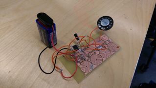
Circuit Arrangement
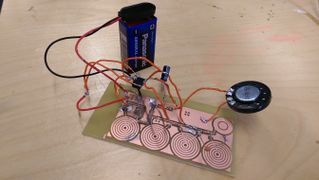


Process
1. Etch the schematic diagram onto the copper plate. For this, I printed the schematic diagram onto the copper place first and then dipped it in acid to get etched.Time duration included 1 1/2 hours.
2. Once our schematic drawing was etched on the copper plate. Schematic 1 diagram was followed to fix the components of the circuit. This was a rather intricate process considering the size of the components and my skill(first timer).
Result
The sound produced by the board was different. The gradation in sound was absent. The sound produced would play if you place your finger on the touchpad and would pause if any of the other touch pads on the circuit were touched. The outcome was 'reversed'.
I tried uploading a video of it didn't work. To see a video of my circuit, please visit my Youtube Channel 'Sneha Arvind'. Thanks!