User:Tim Reuser
Tim Reuser
0891980
Product Design
timreuser.nl
Contents
Project 1: On the body
Draw a body part and design an artifact for this specific part.
The body part I’ve chosen to draw was a hand. For me hands are such important body parts because the serve so many purposes; You can use them to pick something up, feel the shape of something, sense the properties of object, use them to give shape to something, etc.
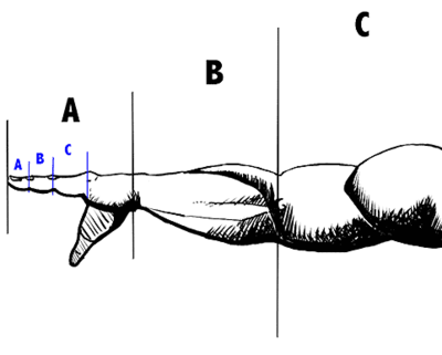
After being put together in a group with Jeroen and Iikay we’ve discussed what the correlation was between each other’s drawings. As Jeroen had drawn finger and Iikay an arm, there was already an obvious connection their physical form. After some brainstorming and research, we decided that the most interesting reference for these body parts are that historically they have been used as tools for measuring and counting. Going back all the way to the antiquity where they used the measurement of their elbow to their fingertip known as a cubit. The cubit was employed as a tool for measuring in many parts of the world however, the size of a cubit was never the same among the course of history, as standardized cubits that have been found ranged up to centimeter from one another. In modern times, there is still a very obvious link between measurements and body parts. Within the imperial system of units (inch, foot, etc.) the use of body parts is still very evident, though the dimensions linked to these body parts have been generalized.
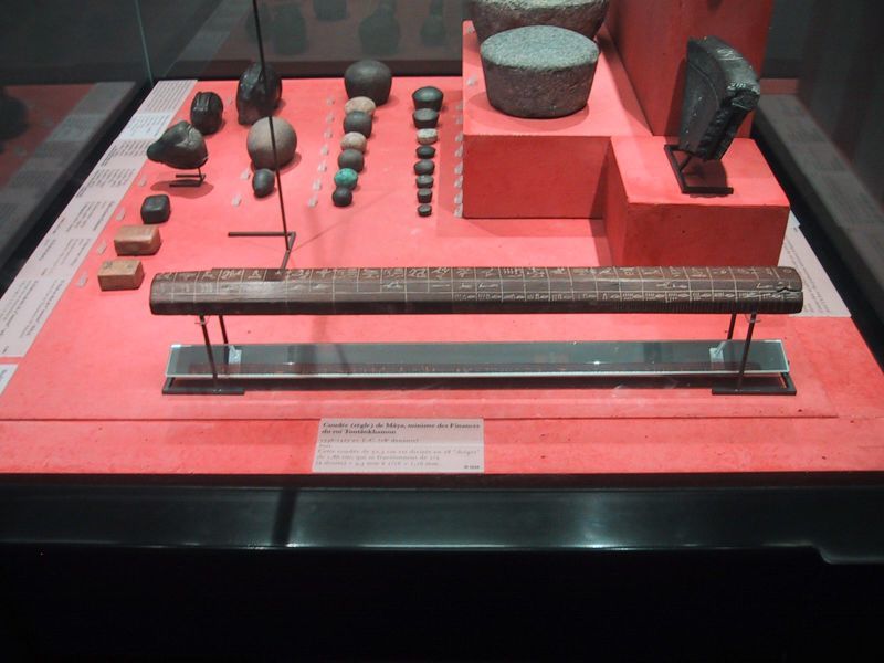
Cubit rod in the Museo Egizio of Turin, showing digit, palm, hand and fist lengths Source: internet, https://en.wikipedia.org/wiki/Cubit
Cubit rod of Maya, 1336-1327 BC (Eighteenth Dynasty) Source: internet, https://en.wikipedia.org/wiki/Cubit
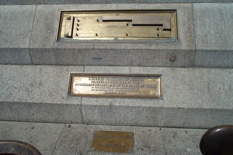
Imperial standards of length 1876 in Trafalgar Square, London. Source: internet, https://en.wikipedia.org/wiki/Imperial_units#/media/File:Imperial_standards_of_length_1876_Trafalgar_Square.jpg
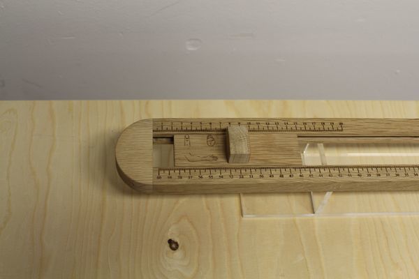
Self-made cubit. Representing the finger in orange, the hand in green and the elbow in red.
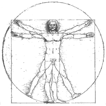
Elaboration on human measurements we came across the well-known Vitruvian man by renaissance artist Leonardo da Vinci. Him having drawn a man in perfect proportions led us to investigate if there was such a thing as a perfect rhythm between body parts. This became the base of our concept for our presentation as explained in the following:
The famous work “L'Uomo Vitruviano” by Renaissance artist Leonardo Da Vinci embodies the ideal human proportions according to rhythm and geometry in analogy to documentations of the ancient Roman architect Marcus Vitruvius, who used human scale as a reference for his constructions. Elaborating on these documentations Da Vinci depicts a man bounded by a square and a circle in which he should fit if his proportions are in harmony with those assumed as the ‘holy ratio’. Accordingly, the square and the circle became a symbol of the Renaissance and architects based their structures on these mathematic figures and dimensions in search for geometric perfection.
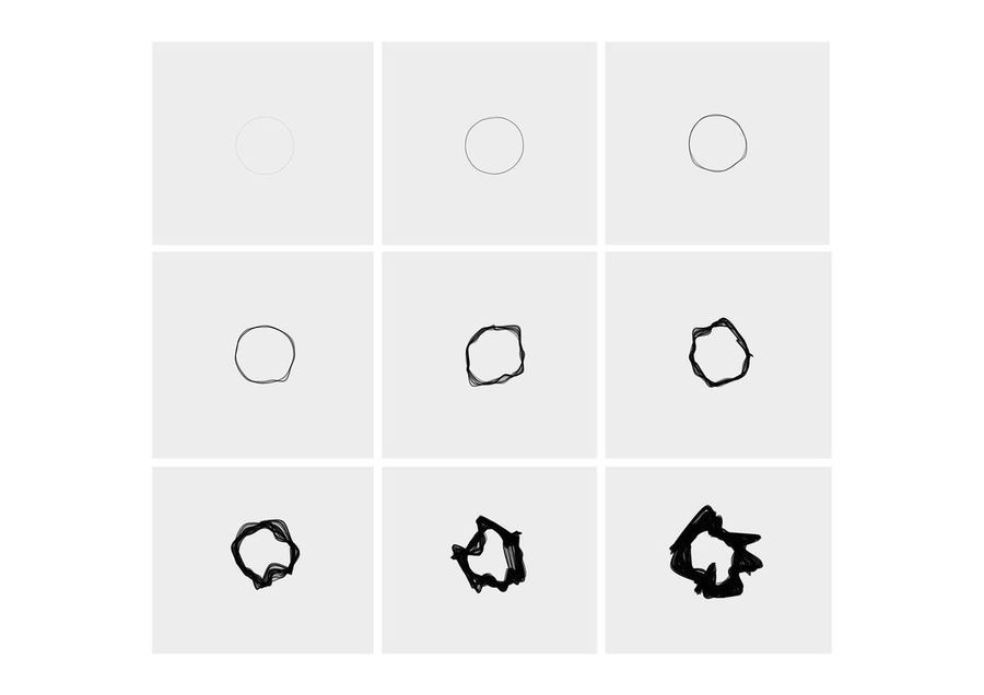
Inspired by this concept we engaged on a study aiming to find a ‘Vitruvian’ among us. By using 3D scanning and performing measurements we’ve collected data, which we then compared to the rhythm and geometry established by Da Vinci.
Palm width equals the width of four fingers
Cubit length equals the width of six palms
Body length equals the length of four cubits
Arm span equals the length of the body
Like the Vitruvian man of Da Vinci we have used a circle as a reference for the perfect proportion. The more the proportions of our subject divert from those specified by Da Vinci, the more distorted the circle becomes.
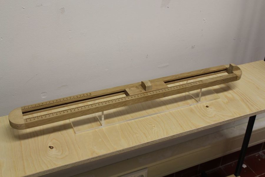
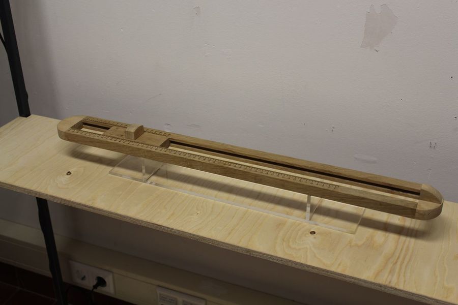
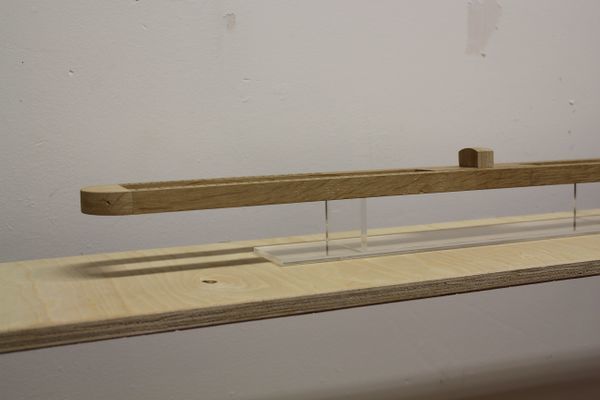
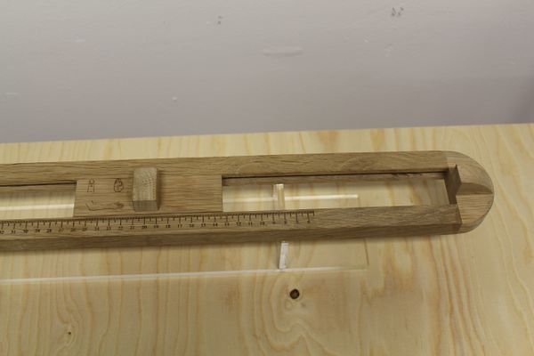
A tool to measure the proportions of the body
Project 2: Inhuman factors/ sensitivity training
Heat Sensor
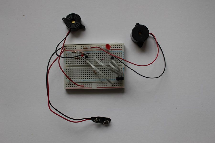
For the first assignment of the second project I made both a heat sensor as well a touch sensor. For the heat sensor I made circuit that consists of a 9V battery serving as power source and a temperature responsive transistor as heat sensing functional component. A potentiometer in the circuit allows adjusting the temperature range (sensitivity setting) of the transistor’s responsiveness. A LED diode is used to monitor temperature changes. It is ‘off’ at the lowest temperature setting and starts to light up brighter and brighter when the temperature rises. In addition to these main components, there are several resistors in the circuit to regulate the flow of current. The circuit of the touch sensor that I fabricated is somewhat similar. Here too, a 9V battery feeds the circuit. The functional component is very simple and consists of two parallel blank wires that when touched connect. When the circuit is closed by the touch of the finger, the current runs both through a LED that lights up as well as through a small speaker mounted in parallel with the LED and producing a signal. Sweaty fingers provide greater conductivity causing brighter light and louder sound. Also this circuit contains several resistors to control current flow.
For the second part of the project and to further explore sensors I teamed up with Alex. Together we decided to elaborate on the heat sensor. After some research and brainstorming we decided that we were both more into exploring heat sensitive materials, which can also be seen as heat sensors, than using a heat sensor to activate any kind of process. We felt that keeping the process basic and using the least number of added elements would make the process optimally transparent. Therefore, we both started looking for materials that were responsive to heat, instead of elaborating on electronic circuits build for heat sensing and heat monitoring.
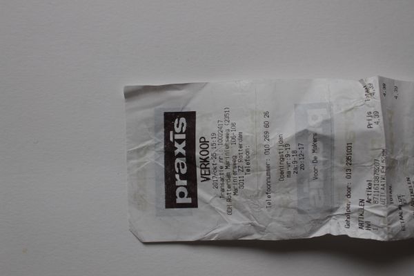
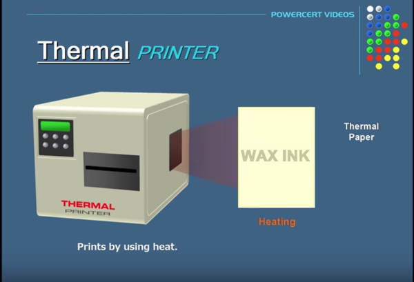
How it started for me is that I remembered that I once tried to iron a receipt to get the wrinkles out. The wrinkles didn’t get our and the receipt turned totally black. I had never asked myself the question why. But in the course of this project it suddenly crossed my mind that the paper used for printing the receipt may have had some kind of heat sensitive coating. Searching the Internet I found that most receipts aren’t printed with traditional ink cartridges, but that the ink is already in the paper and activated by heat. This technique is called thermal printing.
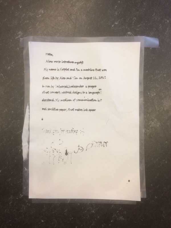
The paper is coated with a wax-based ink that turns black when exposed to heat.
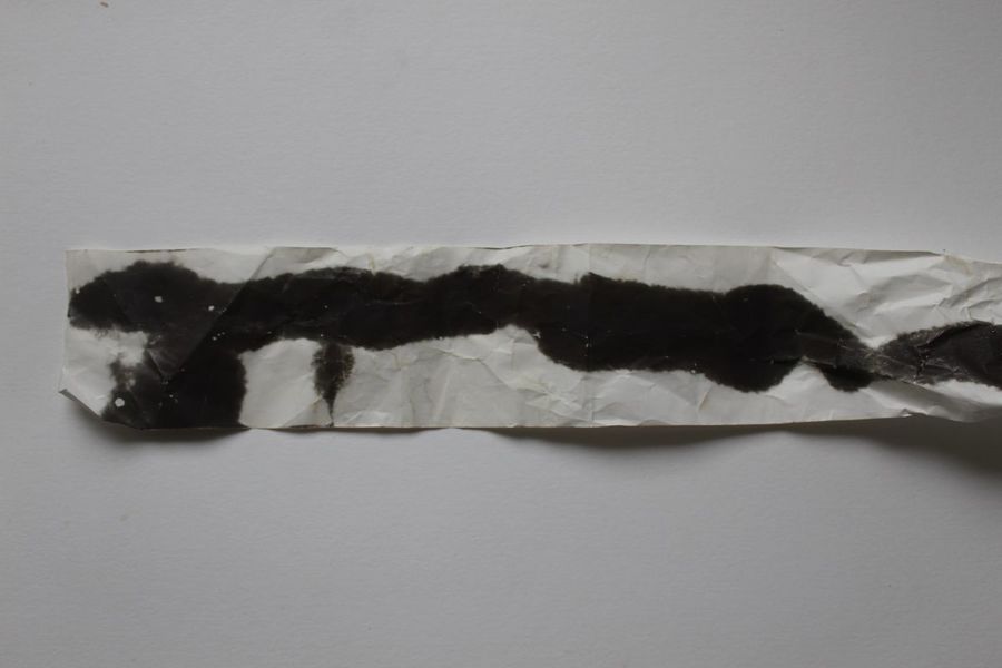
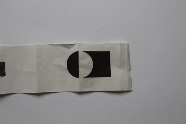
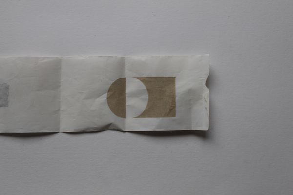
We found this phenomenon quite interesting in relation to materials that act in some way as heat sensors and decided to experiment with it. We got hold of heat sensitive receipt rolls and started testing by holding the paper close to a flame and subsequently putting it under the laser cutter. Exposure to the flame caused big and uncontrollable black patterns, but with the laser cutter we succeeded to produce better-controlled and more accurate results. However, because of the pretty strong laser beam heat we had to flip the paper backside up for it would otherwise burn off the entire heat sensitive layer.
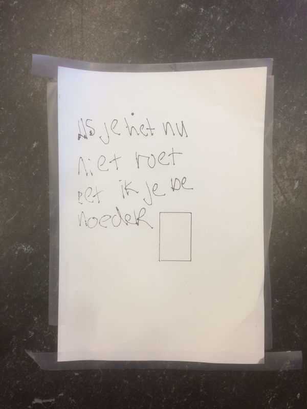
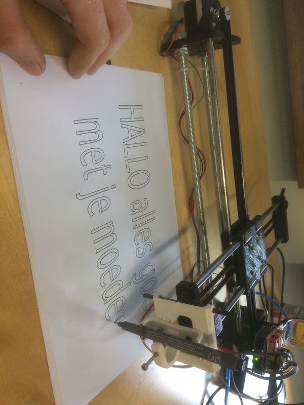
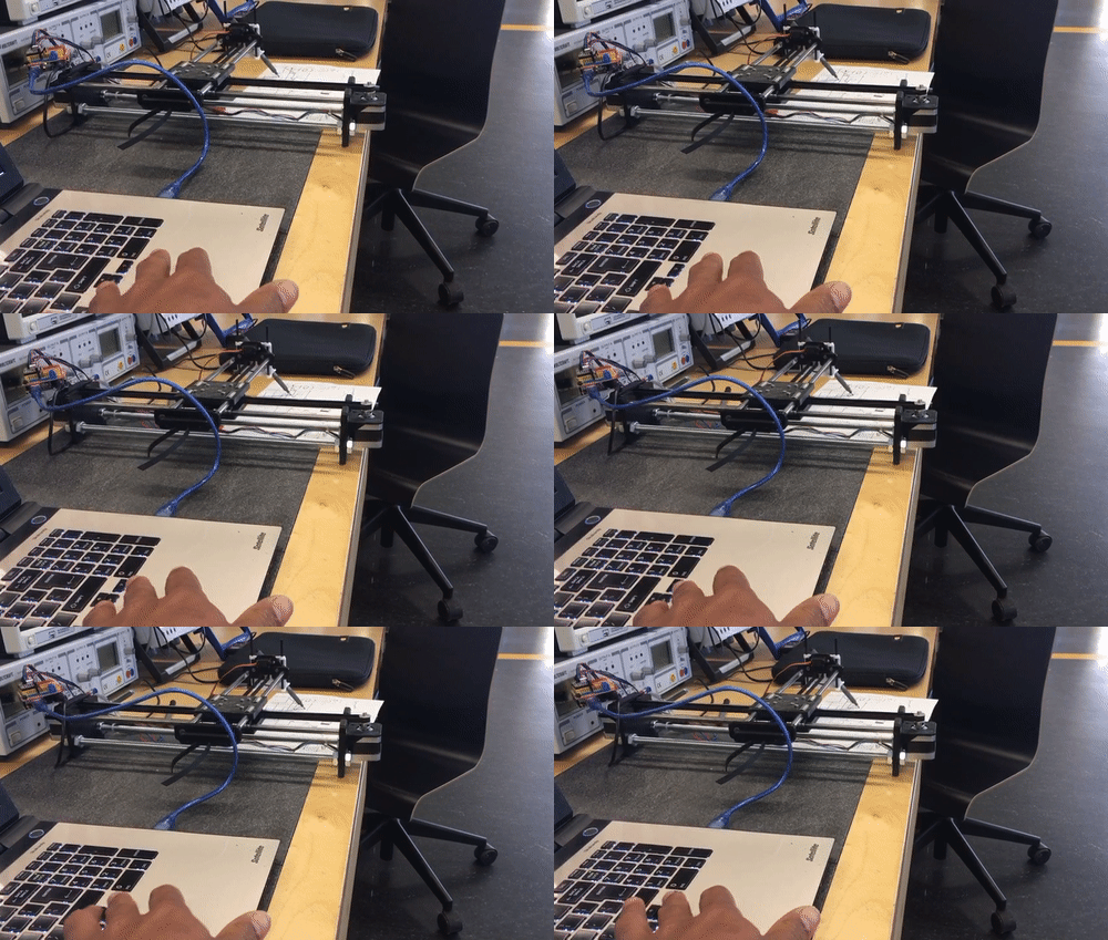
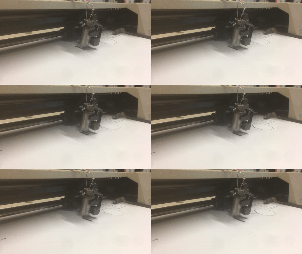
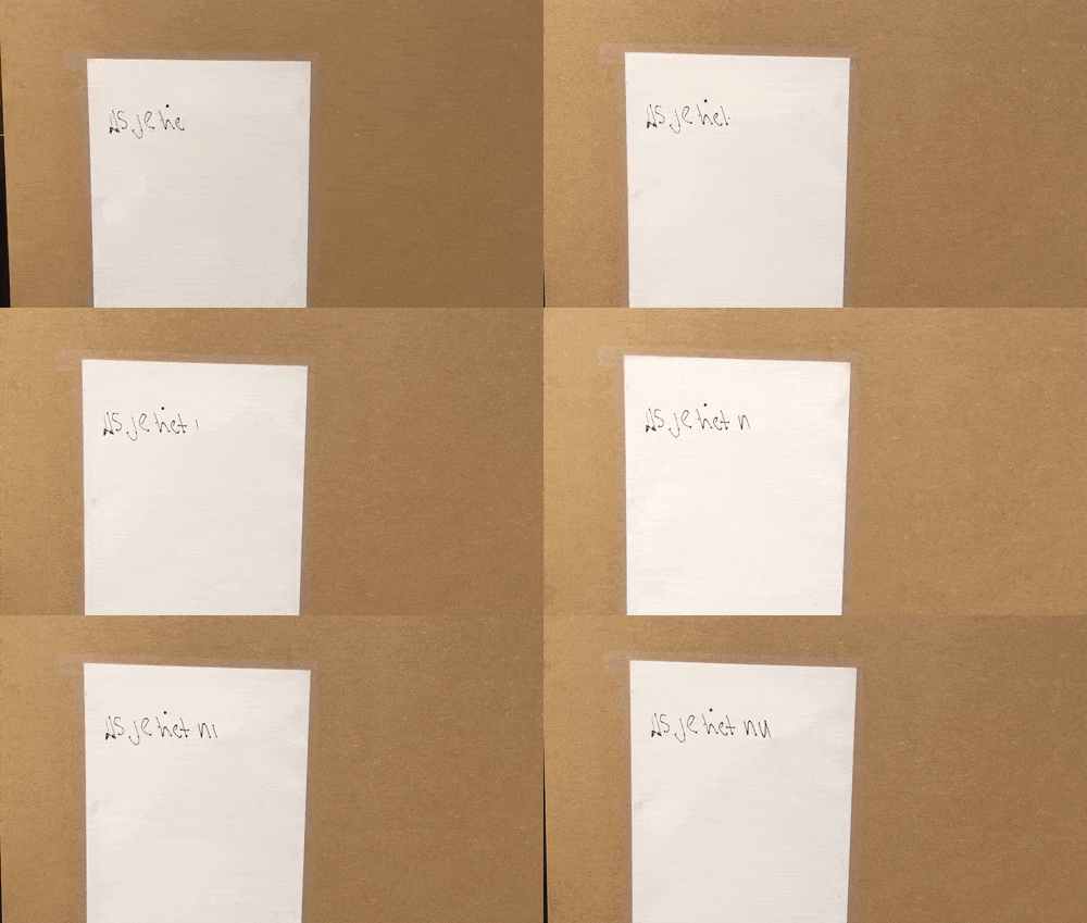
This actually led to the idea of heating the paper from the backside so that the ink would appear on the front side without visible sight of the ‘activating’ heat source. This set up would cause a sort of magic effect as text and illustrations would appear without understanding how. To work out this idea, we bought A4 thermal paper so that we could make bigger size prints. Also, we decided that it would be nice to connect the heating element to a plotter thereby creating a stand-alone instrument for writing text and making illustrations.
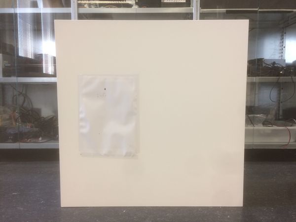
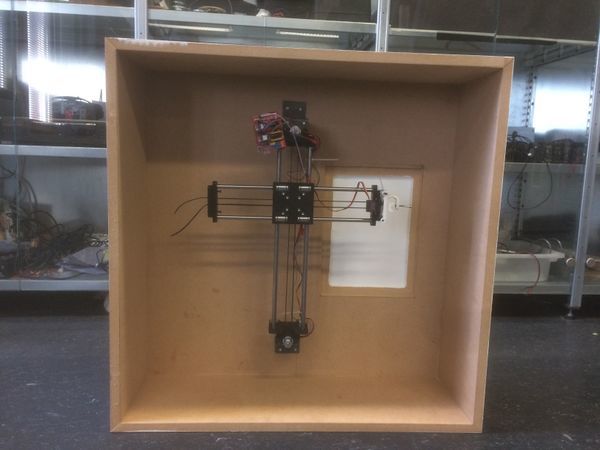
For our idea we used a DIY 4xi-drawing machine and mounted it in a box. A hole was made through which the heating element could reach the paper that covered the hole. This way the heating element controlled by the plotter could reach the paper from the backside and create accurate drawings on the front side.
For the midterms we decided that it would be even better if the machine would be capable to magically draw a poster for the exhibition in real-time. For that purpose, we used a snap frame to hold the poster while being generated.
Project 3: Mind (of) the machine
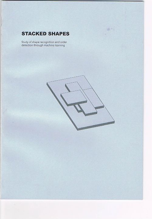 ------> Shape Recognition publication
Project 4: Mica Workshop
Essay: What is your craft?
“In between a raw material and a finished product is the area in which I like to operate most. Taking steps back in established ways of using a material and reinventing it for new use or for new aesthetic values is fundamental in my work.
My work is often based on a certain trouvaille that I get during the process of researching a material or subject and hands-on testing. Whether it’s pushing the boundaries of a material, creating new forms or more conceptual work, the process is always an important factor that is highlighted in the end result.”
I formulated this statement while composing my portfolio during the third year of my studies at Willem de Kooning. Defining my way of working in a few sentences guiding me towards and resulting in receiving the most appropriate internship. That is how I formulated my future objective at that time.
Reflecting on the previous years and detecting a correlation and consistency in my work now stretches beyond convincing people to hire me. The way I formulated my mode of operation has become a gauge for me rationalizing my work. It is a source for inspiration; a criterion for further reflection on study progress and justification of the chosen direction towards my future as product designer.
Even though my choice to follow the minor Digital Craft can be seen as a ‘minor’ detour from my preferred track of operating, as formulated by the statement in my portfolio, my focus hasn’t changed. On the contrary, since then I have gained new experiences and insights that allowed me to interpret my original statement in a broader context and sense, while still using it as a primary, functional, guide.
At first sight, digital technology and its applications seems quite distant from working with tangible materials that can be transformed into equally touchable design products. But, actually, a parallel can be drawn. Most people are able to imagine how a tree trunk is cut to produce timber that is then used as building material for a large range of products. Even, how iron ore is transformed to steel for similar and additional applications. Digital technology is more difficult to grasp, at least for most people, and less easy to access -for me too- so that the idea does not occur to approach digital technology as if it concerns material. As complex as the digital world manifests to the laymen, in essence it can be seen as ground material for artistic work, just like any other material.
Computers commonly use interfaces. These function as translator between computer language and every day language, readable and understandable by humans. However, if we look beyond the interface we find the actual raw material that we can fabricate. If we compare, the other way around, digital technology and tangible materials like wood and iron one can, for instance, imagine timber as an interface. Hidden behind it is the tree, as raw data, c.q. the source material. The timber itself, by its specific nature, feeds us with information and provides a display of what products can potentially be made with it and what tools will be needed. Timber can be sawed, glued together to a larger structure, shaped on a lathe, carved, etc. If the computer interface is seen as a stage between the raw source material and the final product the concept of using the digital interface as such can inspire artists and designers, and open-up new possibilities and technological applications.
My craft is exploring the essentials of materials, reinvention them through acquired knowledge and repurpose them in contemporary society. Conventionally, these materials were ‘naturals’ like wood, metal, and stone, but Digital Craft has allowed me to extend my way of thinking and working through digital technology, because I believe, it can be processed in a similar way as physical materials.
The minor Digital Craft has changed my gaze at this stormy upcoming new technology both by attending the courses as well as by research and experimentation. For myself, I noticed a shift in position, from being a distant observer along the sideline, with no understanding of what is happening behind the interface, to a better aware user able to look at the digital discourse more critically. Newer technologies are often presented as tools to enhance the quality of life and, therefore, it seems axiomatic to incorporate them in our daily life without any further questioning.
My drive is not to force progress through technology; for me, ‘progress’ is too ill defined and too complex for assigning it to a project or product of any nature. My intention is to exploit existing and any form of upcoming technology to create artistic, tangible, accessible, but also symbolic design products.
For the coming quarter (Q14) I am intended to use digital reconstruction technology that is commonly applied to reconstruct ancient archeological findings into images that represent the original appearance as accurately as possible. In my way of working l will try to see if that technology can be used to turn timber -as interface- back to a visual tree. The idea of first dissecting a tree into pieces and subsequently resurrecting that same tree with present day digital technology excites me as a challenging, appropriate, way to explore the human controlled relation between nature and technology.

