Difference between revisions of "Stepcraft"
(Created page with "<slidy theme="a" /> ==Preparation of the first component== For further implementing the first step instruction you need the following materials: * Spindle, eg Proxxon IBS /...") |
|||
| Line 10: | Line 10: | ||
* Workpiece material such as plywood with a thickness of 3 mm Alternatively, you can perform your first test with a pen plotter. | * Workpiece material such as plywood with a thickness of 3 mm Alternatively, you can perform your first test with a pen plotter. | ||
==Clamping of the workpiece material== | |||
First you put the offer worktop and then the work piece material on the machine table. With the accompanying retainers from the STEPCRAFT fix the two plates on the machine table. The screws have to only be tightened by hand | First you put the offer worktop and then the work piece material on the machine table. With the accompanying retainers from the STEPCRAFT fix the two plates on the machine table. The screws have to only be tightened by hand | ||
:[[File:Stepcraft1.jpg|600px]] | :[[File:Stepcraft1.jpg|600px]] | ||
==Import the pattern drawing== | |||
In NC WinPc open the "File" menu and then "Open". Navigate to the installation directory of the NC WinPc starter / | In NC WinPc open the "File" menu and then "Open". Navigate to the installation directory of the NC WinPc starter / | ||
USB installation (c: \ WinPc-NC_xxx \) and open the fileMuster02.plt : | USB installation (c: \ WinPc-NC_xxx \) and open the fileMuster02.plt : | ||
| Line 19: | Line 19: | ||
The file consists of an engraved pattern (red line) and the cut out of the work piece (blue line). | The file consists of an engraved pattern (red line) and the cut out of the work piece (blue line). | ||
==Setting the parameters== | |||
*Now open the "Parameters" menu and go to "Misc." and make the following settings: | *Now open the "Parameters" menu and go to "Misc." and make the following settings: | ||
: [[File:Stepcraft2.png|600px]] | : [[File:Stepcraft2.png|600px]] | ||
| Line 28: | Line 28: | ||
*Set the scaling factor for the sample file to 0.2. Thus, the drawing template is reduced to 20% of the original size. | *Set the scaling factor for the sample file to 0.2. Thus, the drawing template is reduced to 20% of the original size. | ||
*Set the Start-/End position as the Origin + Tool lift. | *Set the Start-/End position as the Origin + Tool lift. | ||
==Definition of work piece zero point (X, Y)== | |||
*Highlight the starting point on the work sheet with an "X". Make sure that seen from there from the front there is sufficient travel available to the right and to the rear (at least 50 - 70 mm). | *Highlight the starting point on the work sheet with an "X". Make sure that seen from there from the front there is sufficient travel available to the right and to the rear (at least 50 - 70 mm). | ||
*Open the "Move" menu and then "Jog" (F5) and go manually to the point marked. Move the Z-axis at half maximum height. | *Open the "Move" menu and then "Jog" (F5) and go manually to the point marked. Move the Z-axis at half maximum height. | ||
| Line 36: | Line 36: | ||
*After saving the machine runs automatically 10 mm higher in the Z-axis (tool lift). | *After saving the machine runs automatically 10 mm higher in the Z-axis (tool lift). | ||
*The workpiece coordinates are then X = 0.000, Y = 0.000 and Z = -10.000. | *The workpiece coordinates are then X = 0.000, Y = 0.000 and Z = -10.000. | ||
==Test drive without the use of tools== | |||
*Now open the "Move" menu and go to "Start" (F3). | *Now open the "Move" menu and go to "Start" (F3). | ||
*The machine automatically starts with the processing of the contour. | *The machine automatically starts with the processing of the contour. | ||
Make sure that the spindle can move in the work area without collision. Please also note that for later milling the spindle start is much lower and a collision with the retainers or the Y-rails should be avoided. | Make sure that the spindle can move in the work area without collision. Please also note that for later milling the spindle start is much lower and a collision with the retainers or the Y-rails should be avoided. | ||
==Preparation of the milling spindle== | |||
Tension the milling tool in the spindle. Make sure that you select the correct adapter sleeve, so that the cutter is held tightly. | Tension the milling tool in the spindle. Make sure that you select the correct adapter sleeve, so that the cutter is held tightly. | ||
| Line 48: | Line 48: | ||
:[[File:Stepcraft7.jpg|600px]] | :[[File:Stepcraft7.jpg|600px]] | ||
After the mill has been clamped in the spindle, set the clamping adapter (if required) in the 43 mm spindle taper of the STEPCRAFT. The milling spindle is used in turn in the clamping adapter. Lock the spindle in the spindle with the correct Allen key. | After the mill has been clamped in the spindle, set the clamping adapter (if required) in the 43 mm spindle taper of the STEPCRAFT. The milling spindle is used in turn in the clamping adapter. Lock the spindle in the spindle with the correct Allen key. | ||
==Definition of workpiece zero point (Z)== | |||
*Now open "Jog" (F5) in the "Move" menu: Open the sub-item "Move to" and select Zero Point X / Y. | *Now open "Jog" (F5) in the "Move" menu: Open the sub-item "Move to" and select Zero Point X / Y. | ||
*The machine automatically moves to the previously stored X / Y coordinates ("X"). | *The machine automatically moves to the previously stored X / Y coordinates ("X"). | ||
| Line 56: | Line 56: | ||
*Move the paper back and forth with your fingers. Once the cutter touches the paper, save that point again as the work piece zero point X / Y / Z: | *Move the paper back and forth with your fingers. Once the cutter touches the paper, save that point again as the work piece zero point X / Y / Z: | ||
:[[File:Stepcraft10.png|600px]] | :[[File:Stepcraft10.png|600px]] | ||
==Preparation of the sample component== | |||
In preparation for the first test drive, please proceed as follows: | In preparation for the first test drive, please proceed as follows: | ||
*Check the seating of the workpiece plate | *Check the seating of the workpiece plate | ||
Revision as of 12:21, 25 March 2015
<slidy theme="a" />
Preparation of the first component
For further implementing the first step instruction you need the following materials:
- Spindle, eg Proxxon IBS / E with clamping adapter or alternative spindle
- Cutters for woodworking (spiral cut) with 1 mm diameter or similar tool
- Offer worktop, e.g. out of MDF
- Workpiece material such as plywood with a thickness of 3 mm Alternatively, you can perform your first test with a pen plotter.
Clamping of the workpiece material
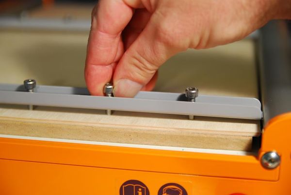
First you put the offer worktop and then the work piece material on the machine table. With the accompanying retainers from the STEPCRAFT fix the two plates on the machine table. The screws have to only be tightened by hand
Import the pattern drawing
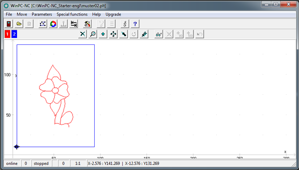
In NC WinPc open the "File" menu and then "Open". Navigate to the installation directory of the NC WinPc starter / USB installation (c: \ WinPc-NC_xxx \) and open the fileMuster02.plt :
The file consists of an engraved pattern (red line) and the cut out of the work piece (blue line).
Setting the parameters
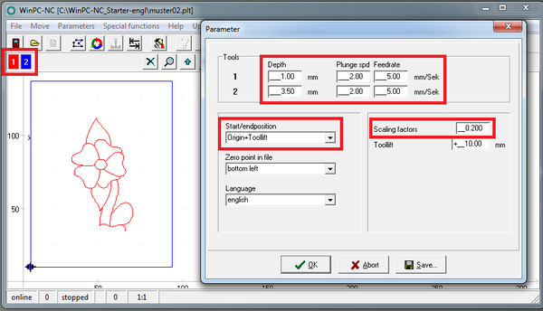
- Now open the "Parameters" menu and go to "Misc." and make the following settings:
- The engraving (tool 1 = red line) is to be set with a depth of 1 mm.
- The clamped workpiece material has a thickness of approximately 3 mm in this example. The cut out is thus a service of 3.5mm (2 tool = blue line).
Note: Numbers with decimal places must be entered with a decimal point. The correct depth setting for tool 2 is therefore 3.5. In this example the pattern is made of plywood or plastic. The in-feed rate / plunge speed is thereby set to 2 mm / sec and the feed rate to 5 mm / s.
- Set the scaling factor for the sample file to 0.2. Thus, the drawing template is reduced to 20% of the original size.
- Set the Start-/End position as the Origin + Tool lift.
Definition of work piece zero point (X, Y)
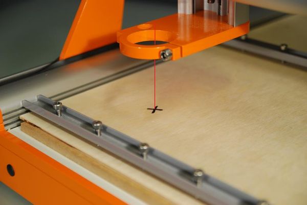
- Highlight the starting point on the work sheet with an "X". Make sure that seen from there from the front there is sufficient travel available to the right and to the rear (at least 50 - 70 mm).
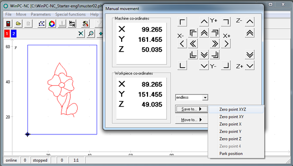
- Open the "Move" menu and then "Jog" (F5) and go manually to the point marked. Move the Z-axis at half maximum height.
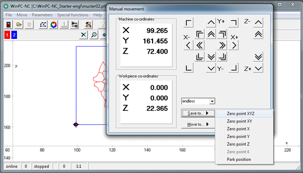
- Save this using "Save to" as the zero point X / Y / Z.
- After saving the machine runs automatically 10 mm higher in the Z-axis (tool lift).
- The workpiece coordinates are then X = 0.000, Y = 0.000 and Z = -10.000.
Test drive without the use of tools
- Now open the "Move" menu and go to "Start" (F3).
- The machine automatically starts with the processing of the contour.
Make sure that the spindle can move in the work area without collision. Please also note that for later milling the spindle start is much lower and a collision with the retainers or the Y-rails should be avoided.
Preparation of the milling spindle
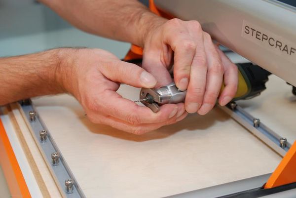
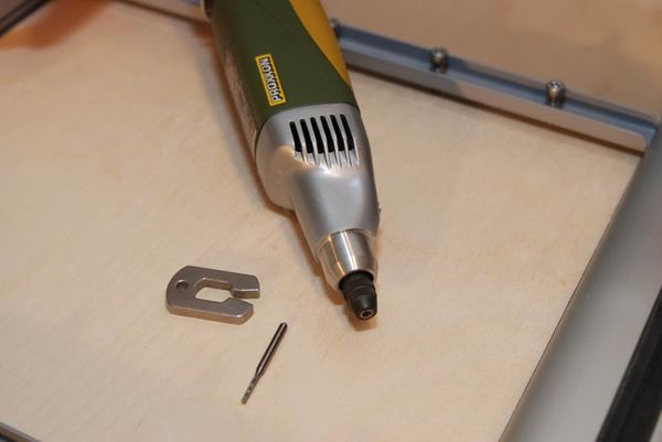
Tension the milling tool in the spindle. Make sure that you select the correct adapter sleeve, so that the cutter is held tightly.
The cutter should always be inserted as far as possible into the chuck.
After the mill has been clamped in the spindle, set the clamping adapter (if required) in the 43 mm spindle taper of the STEPCRAFT. The milling spindle is used in turn in the clamping adapter. Lock the spindle in the spindle with the correct Allen key.
Definition of workpiece zero point (Z)
- Now open "Jog" (F5) in the "Move" menu: Open the sub-item "Move to" and select Zero Point X / Y.
- The machine automatically moves to the previously stored X / Y coordinates ("X").
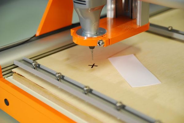
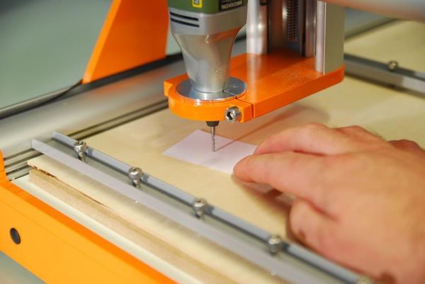
- Take a piece of paper, put this on the work sheet and proceed slowly manually in the Z-axis downwards towards the workpiece:
- Move the paper back and forth with your fingers. Once the cutter touches the paper, save that point again as the work piece zero point X / Y / Z:
Preparation of the sample component
In preparation for the first test drive, please proceed as follows:
- Check the seating of the workpiece plate
- Preselect the speed of the spindle to 15,000 rev / min.
- Turning the spindle on
- Now open the "Move" menu and go to "Start" (F3).
The machine moves to the workpiece zero point X = 0.000 and Y = 0.000, and then in the Z-axis for the first step (= engraving, red line) down to Z = 1.000. The work in progress is displayed in%:
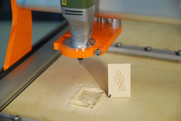
After completion of the work process, the system automatically moves to the workpiece zero point. Turn off the spindle and remove the workpiece.
Read the complete [documentation].
