Difference between revisions of "User:Timo van Dijk"
| (36 intermediate revisions by the same user not shown) | |||
| Line 5: | Line 5: | ||
[[/aantekeningen | aantekeningen ]] | [[/aantekeningen | aantekeningen ]] | ||
| − | + | =Museum Of Fantastic Forgeries= | |
Wang Guangle - Coffin Paint | Wang Guangle - Coffin Paint | ||
| Line 28: | Line 28: | ||
Conditional design is a way of designing work which focusses more on the process instead of the product. The way how the work is evolving or is being created has more importance than the medium. Proces, logic and input are three key aspects of the design. The proces is the product, logic is the tool and input is the material. | Conditional design is a way of designing work which focusses more on the process instead of the product. The way how the work is evolving or is being created has more importance than the medium. Proces, logic and input are three key aspects of the design. The proces is the product, logic is the tool and input is the material. | ||
| − | ==Process== | + | ==Process of the machine== |
For the reconstruction I wanted to use a mechanical way of creating the piece because of the conditional design. A computer works with a design of conditions which are based on logic. The movements of a brush to reporduce the work should be so simple to translate it to conditions for a robot. So I decided to use an Arduino and create a robot who could paint the strokes for the work. | For the reconstruction I wanted to use a mechanical way of creating the piece because of the conditional design. A computer works with a design of conditions which are based on logic. The movements of a brush to reporduce the work should be so simple to translate it to conditions for a robot. So I decided to use an Arduino and create a robot who could paint the strokes for the work. | ||
| Line 37: | Line 37: | ||
[[File:L298_pl.jpg|thumb|right|L298]] | [[File:L298_pl.jpg|thumb|right|L298]] | ||
| − | With a breadboard and a Arduino Uno I started to prototype the basic fucntions for the machine. I used the schematics of the L298 to connect the motor and the Arduino in the right way. The L298 has fifteen pins that takes six in- and four outputs. The four outputs can drive two DC motors and the inputs control the direction. A useful aspect of the L298 is that you can connect a seperate power source for the motor so you can put different voltages than the 5V of the arduino and don't have interference in the electric currents between the motor and the Arduino. The Arduino isn't powerfull enough to power itself and the motor simultaniously. So for this setup it's necesary to have a seperate power source for the motor. I used an old AC/DC multi-voltage adapter on which you can choose a voltage between 1,5V and 12V. I measured the motor's current to see on what voltage it performs best for the L298. At 5V it uses on full load | + | With a breadboard and a Arduino Uno I started to prototype the basic fucntions for the machine. I used the schematics of the L298 to connect the motor and the Arduino in the right way. The L298 has fifteen pins that takes six in- and four outputs. The four outputs can drive two DC motors and the inputs control the direction. A useful aspect of the L298 is that you can connect a seperate power source for the motor so you can put different voltages than the 5V of the arduino and don't have interference in the electric currents between the motor and the Arduino. The Arduino isn't powerfull enough to power itself and the motor simultaniously. So for this setup it's necesary to have a seperate power source for the motor. I used an old AC/DC multi-voltage adapter on which you can choose a voltage between 1,5V and 12V. I measured the motor's current to see on what voltage it performs best for the L298. At 5V it uses on full load 500mAh. The L298 can handle 600mAh before it starts overheating, so my maximum voltage should be 5V to 6V. |
[[File:Printrail.JPG | 300px]][[File:Printtest.JPG | 300px]][[File:Printarduino.JPG | 300px]] | [[File:Printrail.JPG | 300px]][[File:Printtest.JPG | 300px]][[File:Printarduino.JPG | 300px]] | ||
| − | I build two supports from wood for the printer rail and glued the two switches to the sides so the printer head would touch them at the end. For this I wrote a code for the Arduino that if the switch was hit the motor would go the other way. | + | I build two supports from wood for the printer rail and glued the two switches to the sides so the printer head would touch them at the end. For this I wrote a code for the Arduino that if the switch was hit, the motor would go the other way. |
| + | |||
| + | With this I made a test with the same technique as Guangle, painting a stroke, letting it dry and add the second stroke in the other color. I did this for a day, but I was too impatient so the paint mixed some times and became gray strokes. The problem was that the brushes had to be switched every time otherwise they would dry out, and I couldn't automate it that it could switch brushes on its own. | ||
| + | |||
| + | The Arduino code: | ||
| + | <nowiki>int pin2 = 2; | ||
| + | int pin3 = 3; | ||
| + | int switsj1; | ||
| + | int switsj2; | ||
| + | int left = 0; | ||
| + | |||
| + | void setup (){ | ||
| + | |||
| + | pinMode(pin3,OUTPUT); | ||
| + | pinMode(pin2,OUTPUT); | ||
| + | pinMode(A0, INPUT); | ||
| + | pinMode(A5, INPUT); | ||
| + | Serial.begin(9600); | ||
| + | } | ||
| + | |||
| + | void loop(){ | ||
| + | switsj1 = analogRead(A0); | ||
| + | switsj2 = analogRead(A5); | ||
| + | |||
| + | if(switsj1 >= 1021){ | ||
| + | left = 1; | ||
| + | }else if(switsj2 >= 1021){ | ||
| + | left = 0; | ||
| + | } | ||
| + | |||
| + | if(left == 1){ | ||
| + | digitalWrite(pin2,HIGH); | ||
| + | digitalWrite(pin3,LOW); | ||
| + | }else{ | ||
| + | digitalWrite(pin3,HIGH); | ||
| + | digitalWrite(pin2,LOW); | ||
| + | } | ||
| + | |||
| + | delay(100); | ||
| + | } </nowiki> | ||
| + | |||
| + | I resumed with smaller brushes in hope that the strokes would be more gentle and managable. I made several experiments with these brushes. The smallers sizes paid of and the lines were more crisp and powerfull. I upgraded the machine after that with a second motor that would pull the canvas along the printer head. I did this by attaching the paper-motor from the printer behind the bridge of the head and attach some rope to the axis and the canvas. The motor was controlled bij the second in- and output from the L298. I reprogrammed the Arduino so it would pull the canvas for a short moment after the head went forth and back some times. With this the machine was more autonomous and produced the lines on the canvas. | ||
| + | |||
| + | [[File:IMG_1088.JPG | 250px]][[File:IMG_1092.JPG | 250px]][[File:IMG_1096.JPG | 250px]][[File:IMG_1100.JPG | 250px]] | ||
| + | |||
| + | With the machine now working on its own I noticed how fast it filled the canvas and made more experiments varying the amount of paint and speed. In the end I only used black strokes and took the white from the canvas instead of white paint. This because the white paint made it more blurry and dirty. I reprogrammed the Arduino for the last experiments to make shorter pulse for moving the canvas so the lines would be more close to each other. Through a programming mistake that I made, the canvas moved while the head was still in the middle. This created some interesting patterns. It was nice to see that the error made new things by coincidence, but I fixed the program for the ast experiment. | ||
| + | With the last piece of canvas that was left, I used a marker to produce the lines. The effect was interesting because it was more precise than the brush, but the ink from the marker spreaded out a little bit on the canvas, which made the pattern more interesting. | ||
| + | |||
| + | The final Arduino code: | ||
| + | <nowiki> | ||
| + | int pin2 = 2; | ||
| + | int pin3 = 3; | ||
| + | int canvas1 = 7; | ||
| + | int canvas2 = 8; | ||
| + | int switsj1; | ||
| + | int switsj2; | ||
| + | int left = 0; | ||
| + | int moveCanvas = 0; | ||
| + | |||
| + | |||
| + | |||
| + | void setup (){ | ||
| + | |||
| + | pinMode(pin3,OUTPUT); | ||
| + | pinMode(pin2,OUTPUT); | ||
| + | pinMode(canvas1, OUTPUT); | ||
| + | pinMode(canvas2, OUTPUT); | ||
| + | pinMode(A0, INPUT); | ||
| + | pinMode(A5, INPUT); | ||
| + | Serial.begin(9600); | ||
| + | } | ||
| + | |||
| + | void loop(){ | ||
| + | switsj1 = analogRead(A0); | ||
| + | switsj2 = analogRead(A5); | ||
| + | |||
| + | if(switsj1 >= 1021){ | ||
| + | left = 1; | ||
| + | moveCanvas++; | ||
| + | }else if(switsj2 >= 1021){ | ||
| + | left = 0; | ||
| + | moveCanvas++; | ||
| + | |||
| + | delay(500); | ||
| + | |||
| + | if(moveCanvas >= 6){ | ||
| + | digitalWrite(pin3,LOW); | ||
| + | digitalWrite(pin2,LOW); | ||
| + | Serial.println("Move"); //debugging | ||
| + | digitalWrite(canvas1, HIGH); | ||
| + | digitalWrite(canvas2, LOW); | ||
| + | delay(100); | ||
| + | digitalWrite(canvas1, LOW); | ||
| + | moveCanvas = 0; | ||
| + | }else{ | ||
| + | Serial.println("No move"); //debugging | ||
| + | } | ||
| + | } | ||
| + | |||
| + | if(left == 1){ | ||
| + | digitalWrite(pin2,HIGH); | ||
| + | digitalWrite(pin3,LOW); | ||
| + | }else{ | ||
| + | digitalWrite(pin3,HIGH); | ||
| + | digitalWrite(pin2,LOW); | ||
| + | moveCanvas++; | ||
| + | } | ||
| + | |||
| + | delay(500); | ||
| + | } </nowiki> | ||
| + | |||
| + | ==The digital Pattern== | ||
| + | |||
| + | For my own interpetation I wanted to give life to the painting by creating something that would take the image and let it evolve. I came by the principle of "Turing Patterns". Alan Turing was a biologist who created rules behind the creation of patterns in nature like those of zebra's or fish skins. He created a scientific model which shows how two substances create patterns by reacting and spreading out. This model is called 'Reaction-diffusion system". In computer graphics this model comes back in fluid simulation and programming. | ||
| + | |||
| + | I found several processing examples which showed the power behind the system. These create simple patterns based on the Turing Pattern or complex patterns which are called Multi-scale Turing Patterns. | ||
| + | |||
| + | A pattern is formed by the value of each pixel. Through each step of computing, every pixel's value gets recalculated based on the rules of concentration, activation and inhibitation. Each rule's result is based on the avarge values of the surrounding pixels. For example, if the surrounding pixels have low concentration the pixel gets a higher value. Each rule looks at different scale around the the pixel, creating the organic variety. | ||
| + | |||
| + | A multi-scale pattern is created by applying these calculations on different scales. Each pixel gets multiple iterations on different scales, which in the end are avareged as a final value. With this even more complex patterns are created. | ||
| + | |||
| + | Jonatham McCabe wrote a short paper about Turing's priniciple in programming and explains the idea more precise. [http://www.jonathanmccabe.com/Cyclic_Symmetric_Multi-Scale_Turing_Patterns.pdf Link to pdf] | ||
| + | |||
| + | The Java codes that apply these kinds of rules are different in each processing example that I could find, as well as their resulting patterns. | ||
| + | I used one of the examples (made by Bitcraft) as a base to experiment with the code and find interesting results for my reporduction. After trying to figure out how the code works (which I still don't fully get), I started adapting it by instead of starting with random values for the pixels, loading the pixels of an image file. I created two kinds of files to try out, one with lines that had a bit of organic variation and another one that consisted of static black and white lines. | ||
| + | I noticed that the one with organic lines evolved back in the original pattern of the sketch, so the rules in the code always create a certain type of pattern if there is a small amount of variation in the pixel values of the image. The other image created a different, linear pattern. Because of the static lines, the pattern only evolved in one dimension, creating a sort of line play which moves around and reacts to eachother. | ||
| + | |||
| + | [[File:living3.jpg | 250px]][[File:living1.png | 250px]][[File:living4.jpg | 250px]][[File:living2.png | 250px]] | ||
| + | |||
| + | I found this very interesting that these rules are so sensitive to the position and value of the initial pixels and that each image shows it's own pattern and life with these rules. | ||
| + | |||
| + | ==The Plotter== | ||
| + | |||
| + | As as summum of the printer machine from my proces, the plotter could do way more. In the Interaction station was an old HP Draftmaster plotter from the Graphic workstation. The machine was introduced in 1987 as the most advanced HP plotter on the market. By now it's an old dinosaur with remarkable power once you get it working. And that was the challange, to get it working. | ||
| + | |||
| + | Brigit pointed me to Beam, who already did a class for processing and plotters, and created a blog with the explanation and expamples. I used this blog and the example processing sketches as a start. | ||
| + | |||
| + | The proces to get it working was mainly trying to make the computer talk to the machine. The plotter only recieves HPGL/2 language, which is a collection of commands that the machine understands. It does this through a serial port, but modern day computers don't have serial ports anymore. The way to solve this is using a USB to Serial cable. These cables have a chip which the computer can see as a serial port to communicate trhough, but for the chip the computer needs a driver to see it. The driver that Beam supplied on the blog costs some dollars nowadays. But I thought my Macbook already had the driver because it could see the chip. Therefore I tried to get everything working on the plotter first, but the plotter is a very delicate machine and gave errors at every turn. When I finally got the plotter working with the help from Wilco, it still didn't receive any data. In the end Simon helped me find the right driver for the cable and so the plotter finally worked. | ||
| + | |||
| + | Now I could let processing draw some lines and send them to the plotter. I made some tests and experiments with the three plotter pens that I could find on some A4's. The results were very interesting ,but I noticed quickly that the pens where old and that there were no others. Eventually time ran out and left me with the experiments while I wanted to experiment more with other variations for the replication. A great dissapointment from the plotter was that it contains so many sensor that if you would tinker with it by attaching markers, it wouldn't work that easily bacause of errors and failsafes. The machine's head can move very fast and throws paper back and forth at high speeds if you want to. I gets jammed quickly if you attach pens or other things. A following step would be making pens with different mediums that fit in the machines head. | ||
| + | |||
| + | =Written Assignment= | ||
| + | |||
| + | My craft is animation, creating life from in-animate objects through motion. By studying motion and techniques, I can tell stories, give impressions or create a certain emotion. | ||
| + | My main focus lies on creating interesting images through different techniques and methods. These techniques are most times computer related and are orientated around 3D animation. For the last couple of years I learned several ways of animating and found my own interests and ways of producing my ideas through this medium. After animating on the traditional way with pencil and paper I got more interested in fast ways of producing computer generated images due to the efficiency and possibilities of the computer based productions. The flexibility of using countless software packages together and combining these to find new ways of creating images or film interest me a lot. I try to expand my knowledge by getting to know more methods and techniques to create new things. | ||
| + | |||
| + | My craft almost lives in a medium on its own, film. Motion is very difficult to communicate trough only one image, so showing multiple images is a necessity. A story contains a lot of motion, therefore film is the best to fit with animation. But animation can also be created without film. In essence it means creating life with motion, so creating a physical motion (like robotics) can also be seen as animation. Because of this, animation can be applied in a very broad way, it does not necessarily have to been seen as something digital. So techniques vary a lot from analog to digital, with each its own different techniques and methods. Animatronics and puppets are for example analog techniques that involve physical motion and use physical power as a tool. Hand drawn, stop-motion, digital 2D/3D animation, motion graphics and visual effects are more techniques that involve digitalization or the computer as a main tool, and are more common in the craft of animation. | ||
| + | |||
| + | There are a lot of techniques and methods in animation, the use of material and tools have great influence for the end result and these can vary from analog to digital or can even be combined to create new things. | ||
| + | |||
| + | Animation is a craft that expands really fast. Over the last twenty years, animation made a giant leap forward in the movie industry with the use of computers. Nowadays there are no films that don't contain a form of animation, but most times people are not aware of things that are animated. A lot of commercials use animation or motion graphics in big or in small amounts. Animation is not only the classic Disney movies or cartoons from earlier, but almost everywhere around you. With the progression of the digital world, more and more things are developed that contain animation. From interfaces to videogames, a lot of things contain movement and needs to be animated. So the borders of animation keeps expanding with the growing digital culture. The future holds a lot of new possibilities and ways of using animation due to the improvement in software and new purposes. | ||
| + | |||
| + | Throughout history animation had a lot of development. It became well known by Disney and his movies and was a really specialized technique of making film due to analog ways of producing and the time consuming work. So during the last decade the market was mostly dominated by Disney. But during these times there were some artist who took animation as something else as Disney did. More abstract. | ||
| + | Oskar Fischinger was one of the first abstract animator before the WOII. He created a new form of using animation, together with music. He animated shapes frame by frame underneath a camera to visualize the music to which it was animated. He did this in an extremely graphic way, with lines forming into cubes, circles flying over the screen and shapes disappearing on beats of music. He was the first to look at music and film at this way. | ||
| + | During the second half of the last decade this combination of music with film started to turn into video clips of bands and artists, and things inspired by Fischinger's abstract films were not seen so much. | ||
| + | |||
| + | Until the last couple of years, when live video technique developed quickly and electronic music was fit for live visuals. Nowadays abstract animation is made based on music, and is shown live together. Its the same idea as Fischinger had in the 30's, but now with an extra value of live performance, made possible by the modern computers. A lot of visual artist do performances with visuals inspired by Fischinger animations. | ||
| + | |||
| + | Newer technologies don't have a direct influence to animation but do open for example new possibilities for visual results. A laser cutter or 3D printer gives a animator new ways of producing material for an animation. You can quickly cut templates to create drawings or print several shapes to create a stop-motion animation. These sort of new technologies open new possibilities but don't influence the animation techniques or methods. They mostly speed up production work or give an additive value to the result. | ||
| + | There are some new techniques that stand a bit closer to animation and go more together with each other. Videomapping is a new technique that gives animation easier access to be applied in spacial environments and give animation an extra layer of media. The effect of abstract animation is amplified if it can get out of the screen and move itself around a subject. This is a new addition to animation that interests me and led me to study this technique more and more. As well as visual programming, which is not extremely new, but evolved a lot over the last couple of years. | ||
| + | Combining these two new technologies with old and new animation techniques opens new ways of expressing and applying animation. | ||
| + | These are things I like to experiment with related to new technologies. | ||
| + | |||
| + | |||
| + | =Tools of the trade= | ||
| + | |||
| + | For Tools of the trade I want to create an installation that shows the power of the modern day computer visualisation techniques that are used a lot in animation. An endless amount of world can be created with animation which each can be experienced as a reality. Computer technology is so far developed that 3D computer and animation techniques can create a realism that gets closer and closer to reality in a visual way. The video-game industry and development in graphic computer cards can give the oppurtunity to create this realism in real time. In combination with interactive systems and these rendering techniques, the border between the physical and digital world become more thinner. Thanks to these developments in computer technology, augmented and virtual reality are becoming easier to apply and more convincing. | ||
| + | |||
| + | This installation shows that modern animation techniques and interaction can create a world that mimics the reality. | ||
| + | |||
| + | The main characteristics of the installation: | ||
| + | - Recreation of a reality in a digital way. | ||
| + | - The use of realtime rendering. | ||
| + | - Researching the border between reality and digital worlds. | ||
| + | |||
| + | As a start I visualised a prototype of the installation for myself. The first idea is a projection on a wall or object that functions as a mirror of the physical environment the installation is situated. With the use of head-tracking of the user I want to create the effect of a correct optical effect in the mirror, so when the user changes his position, the reflection that is projected would change corresponding to the position of the user's head. | ||
| + | |||
| + | The most suitable software to create the realtime rendering and interaction is Unity 3D, a game engine which besides creating videogames is also very powerfull for interactive systems. A downside to Unity is the power of the Unreal Engine, another game development software which is more powerfull in rendering reality than Unity, but lacks the flexibility for creating an installation. | ||
| + | |||
| + | ==The prototype== | ||
| + | |||
| + | As a prototype of the assigned sensor (the Kinect) I tried to test the idea of tracking the user's head and let that correspond to a virtual camera. I couldn't get it optical right yet, but the idea worked. It still needs a lot of tinkering and experimenting. | ||
| + | |||
| + | ==Development== | ||
| + | |||
| + | I did a lot of techniqal research on how the relfection should work in Unity. The open source unity wiki gives some example of shaders that show real time relfection, instead of the native cubemap that unity wants for using to calculate reflection on objects. | ||
| + | I found a mirror shader and made some test with it to see what could give the best result. | ||
| + | |||
| + | [[File:Screen_Shot_2014-12-10_at_19.32.41.png | 500px]] | ||
| + | |||
| + | Later on I started to make the firts real test of a space, to see how the effect worked and what sort of problems could arise. By measuring the dimensions and photographing the space for making textures in 3D, I recreated the space with Maya to import it into unity. | ||
| + | |||
| + | [[File:Screen_Shot_2015-01-14_at_19.42.43.png | 500px]] | ||
| + | |||
| + | Then I noticed that Unity lacks the ability to create realtime realistic lighting that simulates light bouncing of objects. The technique called Global Illumination was only available trough expensive plugins or in the unreleased version 5 of Unity. I experimented more on trying to fix the problem in Unity, but best solution would be baking the lighting on the textures in Maya later on. | ||
| + | |||
| + | The test was on a small laptop screen but showed its power. The perspective in 3D was not yet perfect, but a good start. Because of the low placement of the screen only the floor was visible, but looked nice. | ||
| + | |||
| + | [[video]] | ||
| + | |||
| + | After the test I started on making the final 3D environment of the space at V2 for final exhibition. I spend a small afternoon taking pictures of the space and trying to solve the problem for lighting. Because the exhibtion's lighting would be different, I tried to cappture the space in a most neutral lighting, to add specific lighting later on. | ||
| + | |||
| + | But the space was really big and made it harder to make a realistic looking replica in 3D due the lack of time. The best solution was to scale down the project and use a smaller part in the space to project. This gave new aspects of the installation that worked actually better, as more detail could be displayed and the interaction would be more intimate. | ||
| + | |||
| + | =Reflection document Tools of the Trade= | ||
| + | [http://opensource.wdka.nl/mediawiki/images/8/8f/Reflection_document_DC-TotT_Timo_van_Dijk.pdf Reflection document link] | ||
Latest revision as of 10:36, 19 January 2015
Contents
Museum Of Fantastic Forgeries
Wang Guangle - Coffin Paint
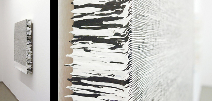
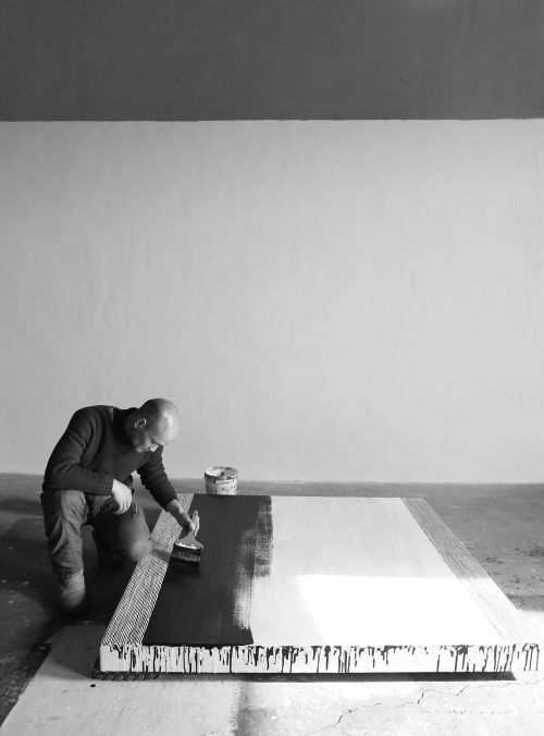
Coffin Paint is a serie of paintings based on the production idea of painting multiple layers of acrylic paint over a period of time. The piece Coffin Paint 131127 (2013) I chose is build out of strokes of white and black paint which Guangle applied two times a day, creating a pattern of thin organic lines. The power behind his series of paintings is the idea and production behind it. It is based on an old Chinese part of culture, in which the Chinese prepare their coffins during their last years.
""...the "Coffin Paints" have a very specific cultural reference: It is customary for some Chinese, as they reach late middle age, to purchase their coffin and repaint it every year, thus hoping to achieve longevity. Wang imagines that his pigment asks to live.""
-mutualart.com 2009 Link-
Guangle used this idea of painting to create different paintings with the same technique.
In a way his way of producing the paintings can be seen as a form of conditional design, where he as an artist restricts himself with a set of conditions on how to produce his work. By applying a layer of white paint, and then wait for half a day for the black layer to build up a whole canvas could be translated as a set of conditions.
Conditional Design
Conditional design is a way of designing work which focusses more on the process instead of the product. The way how the work is evolving or is being created has more importance than the medium. Proces, logic and input are three key aspects of the design. The proces is the product, logic is the tool and input is the material.
Process of the machine
For the reconstruction I wanted to use a mechanical way of creating the piece because of the conditional design. A computer works with a design of conditions which are based on logic. The movements of a brush to reporduce the work should be so simple to translate it to conditions for a robot. So I decided to use an Arduino and create a robot who could paint the strokes for the work.
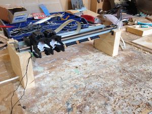
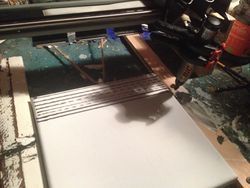
I bought a secondhand printer and took the rail for the printerhead to reconstruct it for the brush to hold and move sideways. The brush only needs to move from right to left and the other way around to paint the work.
I hoped that there would be a steppermotor inside the printer to get a good control over the brush. But both motors inside were normal DC motors, so I had to find an alternative to use these and let them go into two directions, left and right. For this I needed to use a motor controller that changes the current of the electricity. After a discussion with a salesman in the electronic shop in Amsterdam I found out that all controllers are very specific and hard to fast and for cheap. After some research I found the type of the controller I needed which is a L298 H-bridge. Due to holidays from shop owners and shops that where out of stock I found my controller in Groningen when I happened to be there.
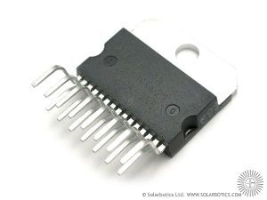
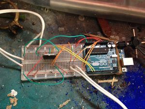
With a breadboard and a Arduino Uno I started to prototype the basic fucntions for the machine. I used the schematics of the L298 to connect the motor and the Arduino in the right way. The L298 has fifteen pins that takes six in- and four outputs. The four outputs can drive two DC motors and the inputs control the direction. A useful aspect of the L298 is that you can connect a seperate power source for the motor so you can put different voltages than the 5V of the arduino and don't have interference in the electric currents between the motor and the Arduino. The Arduino isn't powerfull enough to power itself and the motor simultaniously. So for this setup it's necesary to have a seperate power source for the motor. I used an old AC/DC multi-voltage adapter on which you can choose a voltage between 1,5V and 12V. I measured the motor's current to see on what voltage it performs best for the L298. At 5V it uses on full load 500mAh. The L298 can handle 600mAh before it starts overheating, so my maximum voltage should be 5V to 6V.
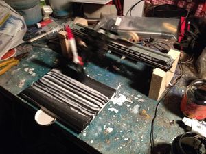
I build two supports from wood for the printer rail and glued the two switches to the sides so the printer head would touch them at the end. For this I wrote a code for the Arduino that if the switch was hit, the motor would go the other way.
With this I made a test with the same technique as Guangle, painting a stroke, letting it dry and add the second stroke in the other color. I did this for a day, but I was too impatient so the paint mixed some times and became gray strokes. The problem was that the brushes had to be switched every time otherwise they would dry out, and I couldn't automate it that it could switch brushes on its own.
The Arduino code:
int pin2 = 2;
int pin3 = 3;
int switsj1;
int switsj2;
int left = 0;

void setup (){

     pinMode(pin3,OUTPUT);
     pinMode(pin2,OUTPUT);
     pinMode(A0, INPUT);
     pinMode(A5, INPUT);
     Serial.begin(9600);
}

void loop(){
  switsj1 = analogRead(A0);
  switsj2 = analogRead(A5);

  if(switsj1 >= 1021){
    left = 1;
  }else if(switsj2 >= 1021){
    left = 0;
  }

  if(left == 1){
    digitalWrite(pin2,HIGH);
    digitalWrite(pin3,LOW);
  }else{
    digitalWrite(pin3,HIGH);
    digitalWrite(pin2,LOW);
  }

  delay(100);
}
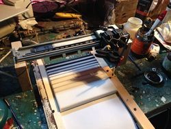
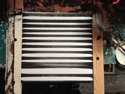
I resumed with smaller brushes in hope that the strokes would be more gentle and managable. I made several experiments with these brushes. The smallers sizes paid of and the lines were more crisp and powerfull. I upgraded the machine after that with a second motor that would pull the canvas along the printer head. I did this by attaching the paper-motor from the printer behind the bridge of the head and attach some rope to the axis and the canvas. The motor was controlled bij the second in- and output from the L298. I reprogrammed the Arduino so it would pull the canvas for a short moment after the head went forth and back some times. With this the machine was more autonomous and produced the lines on the canvas.
With the machine now working on its own I noticed how fast it filled the canvas and made more experiments varying the amount of paint and speed. In the end I only used black strokes and took the white from the canvas instead of white paint. This because the white paint made it more blurry and dirty. I reprogrammed the Arduino for the last experiments to make shorter pulse for moving the canvas so the lines would be more close to each other. Through a programming mistake that I made, the canvas moved while the head was still in the middle. This created some interesting patterns. It was nice to see that the error made new things by coincidence, but I fixed the program for the ast experiment. With the last piece of canvas that was left, I used a marker to produce the lines. The effect was interesting because it was more precise than the brush, but the ink from the marker spreaded out a little bit on the canvas, which made the pattern more interesting.
The final Arduino code:
int pin2 = 2;
int pin3 = 3;
int canvas1 = 7;
int canvas2 = 8;
int switsj1;
int switsj2;
int left = 0;
int moveCanvas = 0;


void setup (){

     pinMode(pin3,OUTPUT);
     pinMode(pin2,OUTPUT);
     pinMode(canvas1, OUTPUT);
     pinMode(canvas2, OUTPUT);
     pinMode(A0, INPUT);
     pinMode(A5, INPUT);
     Serial.begin(9600);
}

void loop(){
  switsj1 = analogRead(A0);
  switsj2 = analogRead(A5);

  if(switsj1 >= 1021){
    left = 1;
    moveCanvas++;
  }else if(switsj2 >= 1021){
    left = 0;
    moveCanvas++;

    delay(500);

    if(moveCanvas >= 6){
      digitalWrite(pin3,LOW);
      digitalWrite(pin2,LOW);
      Serial.println("Move");       //debugging
      digitalWrite(canvas1, HIGH);
      digitalWrite(canvas2, LOW);
      delay(100);
      digitalWrite(canvas1, LOW);
      moveCanvas = 0;
    }else{
      Serial.println("No move");    //debugging
    }
  }

  if(left == 1){
    digitalWrite(pin2,HIGH);
    digitalWrite(pin3,LOW);
  }else{
    digitalWrite(pin3,HIGH);
    digitalWrite(pin2,LOW);
    moveCanvas++;
  }

  delay(500);
}
The digital Pattern
For my own interpetation I wanted to give life to the painting by creating something that would take the image and let it evolve. I came by the principle of "Turing Patterns". Alan Turing was a biologist who created rules behind the creation of patterns in nature like those of zebra's or fish skins. He created a scientific model which shows how two substances create patterns by reacting and spreading out. This model is called 'Reaction-diffusion system". In computer graphics this model comes back in fluid simulation and programming.
I found several processing examples which showed the power behind the system. These create simple patterns based on the Turing Pattern or complex patterns which are called Multi-scale Turing Patterns.
A pattern is formed by the value of each pixel. Through each step of computing, every pixel's value gets recalculated based on the rules of concentration, activation and inhibitation. Each rule's result is based on the avarge values of the surrounding pixels. For example, if the surrounding pixels have low concentration the pixel gets a higher value. Each rule looks at different scale around the the pixel, creating the organic variety.
A multi-scale pattern is created by applying these calculations on different scales. Each pixel gets multiple iterations on different scales, which in the end are avareged as a final value. With this even more complex patterns are created.
Jonatham McCabe wrote a short paper about Turing's priniciple in programming and explains the idea more precise. Link to pdf
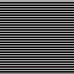
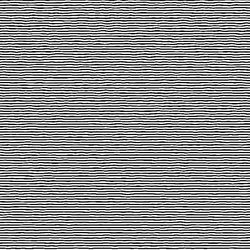
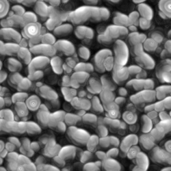
The Java codes that apply these kinds of rules are different in each processing example that I could find, as well as their resulting patterns. I used one of the examples (made by Bitcraft) as a base to experiment with the code and find interesting results for my reporduction. After trying to figure out how the code works (which I still don't fully get), I started adapting it by instead of starting with random values for the pixels, loading the pixels of an image file. I created two kinds of files to try out, one with lines that had a bit of organic variation and another one that consisted of static black and white lines. I noticed that the one with organic lines evolved back in the original pattern of the sketch, so the rules in the code always create a certain type of pattern if there is a small amount of variation in the pixel values of the image. The other image created a different, linear pattern. Because of the static lines, the pattern only evolved in one dimension, creating a sort of line play which moves around and reacts to eachother.
I found this very interesting that these rules are so sensitive to the position and value of the initial pixels and that each image shows it's own pattern and life with these rules.
The Plotter
As as summum of the printer machine from my proces, the plotter could do way more. In the Interaction station was an old HP Draftmaster plotter from the Graphic workstation. The machine was introduced in 1987 as the most advanced HP plotter on the market. By now it's an old dinosaur with remarkable power once you get it working. And that was the challange, to get it working.
Brigit pointed me to Beam, who already did a class for processing and plotters, and created a blog with the explanation and expamples. I used this blog and the example processing sketches as a start.
The proces to get it working was mainly trying to make the computer talk to the machine. The plotter only recieves HPGL/2 language, which is a collection of commands that the machine understands. It does this through a serial port, but modern day computers don't have serial ports anymore. The way to solve this is using a USB to Serial cable. These cables have a chip which the computer can see as a serial port to communicate trhough, but for the chip the computer needs a driver to see it. The driver that Beam supplied on the blog costs some dollars nowadays. But I thought my Macbook already had the driver because it could see the chip. Therefore I tried to get everything working on the plotter first, but the plotter is a very delicate machine and gave errors at every turn. When I finally got the plotter working with the help from Wilco, it still didn't receive any data. In the end Simon helped me find the right driver for the cable and so the plotter finally worked.
Now I could let processing draw some lines and send them to the plotter. I made some tests and experiments with the three plotter pens that I could find on some A4's. The results were very interesting ,but I noticed quickly that the pens where old and that there were no others. Eventually time ran out and left me with the experiments while I wanted to experiment more with other variations for the replication. A great dissapointment from the plotter was that it contains so many sensor that if you would tinker with it by attaching markers, it wouldn't work that easily bacause of errors and failsafes. The machine's head can move very fast and throws paper back and forth at high speeds if you want to. I gets jammed quickly if you attach pens or other things. A following step would be making pens with different mediums that fit in the machines head.
Written Assignment
My craft is animation, creating life from in-animate objects through motion. By studying motion and techniques, I can tell stories, give impressions or create a certain emotion. My main focus lies on creating interesting images through different techniques and methods. These techniques are most times computer related and are orientated around 3D animation. For the last couple of years I learned several ways of animating and found my own interests and ways of producing my ideas through this medium. After animating on the traditional way with pencil and paper I got more interested in fast ways of producing computer generated images due to the efficiency and possibilities of the computer based productions. The flexibility of using countless software packages together and combining these to find new ways of creating images or film interest me a lot. I try to expand my knowledge by getting to know more methods and techniques to create new things.
My craft almost lives in a medium on its own, film. Motion is very difficult to communicate trough only one image, so showing multiple images is a necessity. A story contains a lot of motion, therefore film is the best to fit with animation. But animation can also be created without film. In essence it means creating life with motion, so creating a physical motion (like robotics) can also be seen as animation. Because of this, animation can be applied in a very broad way, it does not necessarily have to been seen as something digital. So techniques vary a lot from analog to digital, with each its own different techniques and methods. Animatronics and puppets are for example analog techniques that involve physical motion and use physical power as a tool. Hand drawn, stop-motion, digital 2D/3D animation, motion graphics and visual effects are more techniques that involve digitalization or the computer as a main tool, and are more common in the craft of animation.
There are a lot of techniques and methods in animation, the use of material and tools have great influence for the end result and these can vary from analog to digital or can even be combined to create new things.
Animation is a craft that expands really fast. Over the last twenty years, animation made a giant leap forward in the movie industry with the use of computers. Nowadays there are no films that don't contain a form of animation, but most times people are not aware of things that are animated. A lot of commercials use animation or motion graphics in big or in small amounts. Animation is not only the classic Disney movies or cartoons from earlier, but almost everywhere around you. With the progression of the digital world, more and more things are developed that contain animation. From interfaces to videogames, a lot of things contain movement and needs to be animated. So the borders of animation keeps expanding with the growing digital culture. The future holds a lot of new possibilities and ways of using animation due to the improvement in software and new purposes.
Throughout history animation had a lot of development. It became well known by Disney and his movies and was a really specialized technique of making film due to analog ways of producing and the time consuming work. So during the last decade the market was mostly dominated by Disney. But during these times there were some artist who took animation as something else as Disney did. More abstract. Oskar Fischinger was one of the first abstract animator before the WOII. He created a new form of using animation, together with music. He animated shapes frame by frame underneath a camera to visualize the music to which it was animated. He did this in an extremely graphic way, with lines forming into cubes, circles flying over the screen and shapes disappearing on beats of music. He was the first to look at music and film at this way. During the second half of the last decade this combination of music with film started to turn into video clips of bands and artists, and things inspired by Fischinger's abstract films were not seen so much.
Until the last couple of years, when live video technique developed quickly and electronic music was fit for live visuals. Nowadays abstract animation is made based on music, and is shown live together. Its the same idea as Fischinger had in the 30's, but now with an extra value of live performance, made possible by the modern computers. A lot of visual artist do performances with visuals inspired by Fischinger animations.
Newer technologies don't have a direct influence to animation but do open for example new possibilities for visual results. A laser cutter or 3D printer gives a animator new ways of producing material for an animation. You can quickly cut templates to create drawings or print several shapes to create a stop-motion animation. These sort of new technologies open new possibilities but don't influence the animation techniques or methods. They mostly speed up production work or give an additive value to the result. There are some new techniques that stand a bit closer to animation and go more together with each other. Videomapping is a new technique that gives animation easier access to be applied in spacial environments and give animation an extra layer of media. The effect of abstract animation is amplified if it can get out of the screen and move itself around a subject. This is a new addition to animation that interests me and led me to study this technique more and more. As well as visual programming, which is not extremely new, but evolved a lot over the last couple of years. Combining these two new technologies with old and new animation techniques opens new ways of expressing and applying animation. These are things I like to experiment with related to new technologies.
Tools of the trade
For Tools of the trade I want to create an installation that shows the power of the modern day computer visualisation techniques that are used a lot in animation. An endless amount of world can be created with animation which each can be experienced as a reality. Computer technology is so far developed that 3D computer and animation techniques can create a realism that gets closer and closer to reality in a visual way. The video-game industry and development in graphic computer cards can give the oppurtunity to create this realism in real time. In combination with interactive systems and these rendering techniques, the border between the physical and digital world become more thinner. Thanks to these developments in computer technology, augmented and virtual reality are becoming easier to apply and more convincing.
This installation shows that modern animation techniques and interaction can create a world that mimics the reality.
The main characteristics of the installation:
- Recreation of a reality in a digital way.
- The use of realtime rendering.
- Researching the border between reality and digital worlds.
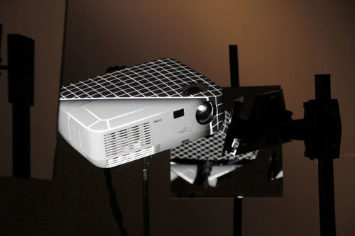
As a start I visualised a prototype of the installation for myself. The first idea is a projection on a wall or object that functions as a mirror of the physical environment the installation is situated. With the use of head-tracking of the user I want to create the effect of a correct optical effect in the mirror, so when the user changes his position, the reflection that is projected would change corresponding to the position of the user's head.
The most suitable software to create the realtime rendering and interaction is Unity 3D, a game engine which besides creating videogames is also very powerfull for interactive systems. A downside to Unity is the power of the Unreal Engine, another game development software which is more powerfull in rendering reality than Unity, but lacks the flexibility for creating an installation.
The prototype
As a prototype of the assigned sensor (the Kinect) I tried to test the idea of tracking the user's head and let that correspond to a virtual camera. I couldn't get it optical right yet, but the idea worked. It still needs a lot of tinkering and experimenting.
Development
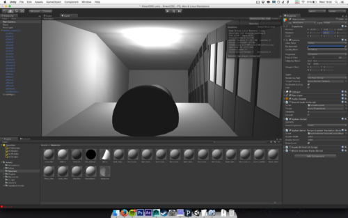
I did a lot of techniqal research on how the relfection should work in Unity. The open source unity wiki gives some example of shaders that show real time relfection, instead of the native cubemap that unity wants for using to calculate reflection on objects. I found a mirror shader and made some test with it to see what could give the best result.
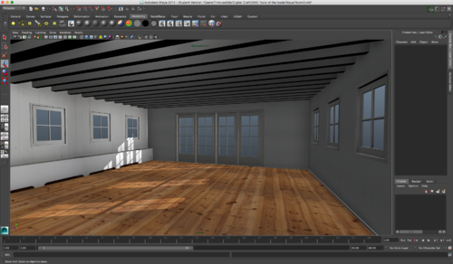
Later on I started to make the firts real test of a space, to see how the effect worked and what sort of problems could arise. By measuring the dimensions and photographing the space for making textures in 3D, I recreated the space with Maya to import it into unity.
Then I noticed that Unity lacks the ability to create realtime realistic lighting that simulates light bouncing of objects. The technique called Global Illumination was only available trough expensive plugins or in the unreleased version 5 of Unity. I experimented more on trying to fix the problem in Unity, but best solution would be baking the lighting on the textures in Maya later on.
The test was on a small laptop screen but showed its power. The perspective in 3D was not yet perfect, but a good start. Because of the low placement of the screen only the floor was visible, but looked nice.
After the test I started on making the final 3D environment of the space at V2 for final exhibition. I spend a small afternoon taking pictures of the space and trying to solve the problem for lighting. Because the exhibtion's lighting would be different, I tried to cappture the space in a most neutral lighting, to add specific lighting later on.
But the space was really big and made it harder to make a realistic looking replica in 3D due the lack of time. The best solution was to scale down the project and use a smaller part in the space to project. This gave new aspects of the installation that worked actually better, as more detail could be displayed and the interaction would be more intimate.
