Difference between revisions of "Joeke Tools Tech 15 16"
| (27 intermediate revisions by the same user not shown) | |||
| Line 4: | Line 4: | ||
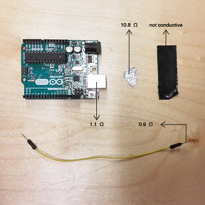
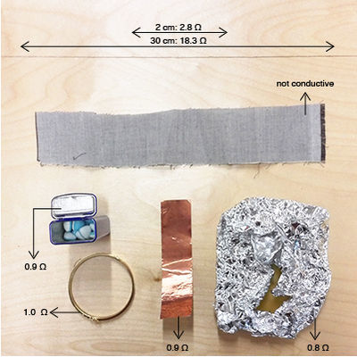
Measuring the resistance of different materials: | Measuring the resistance of different materials: | ||
| + | [[File:Test01-01.jpg|400px]] [[File:Test02-01.jpg|400px]] | ||
== Week #2 Reading Assignment == | == Week #2 Reading Assignment == | ||
| Line 13: | Line 14: | ||
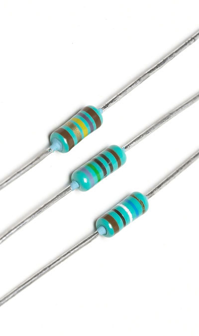
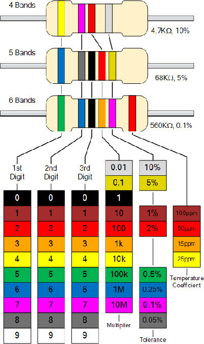
[[File:Resistor.jpg|400px]] [[File:Color code.jpg|400px]] | [[File:Resistor.jpg|400px]] [[File:Color code.jpg|400px]] | ||
| + | |||
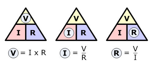
Basic circuit and the Ohms Law: | Basic circuit and the Ohms Law: | ||
| Line 23: | Line 25: | ||
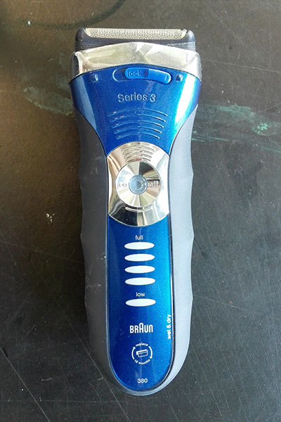
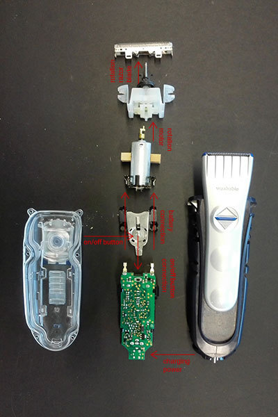
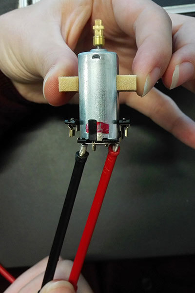
Take apart an electric razor to discover the different parts inside of the device, and how the circuit works: | Take apart an electric razor to discover the different parts inside of the device, and how the circuit works: | ||
| + | [[File:01electric razor.jpg|400px]] [[File:02electric razor parts.jpg|400px]] | ||
| + | |||
| + | |||
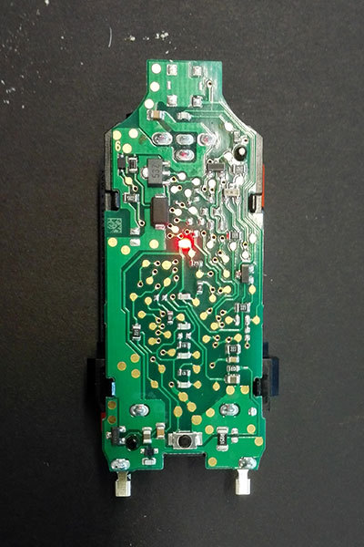
| + | Interesting parts: led light and rotating motor: | ||
| + | |||
| + | [[File:03part led.jpg|400px]] [[File:04part motor.jpg|400px]] | ||
== Week #4 Building a Circuit == | == Week #4 Building a Circuit == | ||
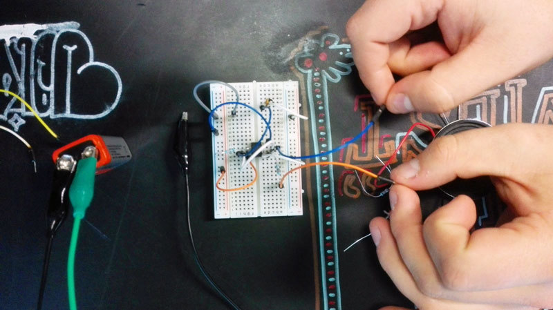
| − | Trying to build a circuit for a speaker. | + | Trying to build a circuit for a speaker: |
| + | |||
| + | [[File:Speaker.jpg|800px]] | ||
| + | |||
| + | == Week #5 Inspiration For Making Circuits == | ||
| + | |||
| + | Discussing different ways to make circuits.<br> | ||
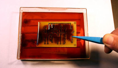
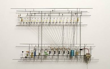
| + | Examples of etching and circuit installations by Peter Vogel: | ||
| + | |||
| + | [[File:Etch01.jpg|412px]] [[File:Vogel01.jpg|388px]] | ||
| + | |||
| + | |||
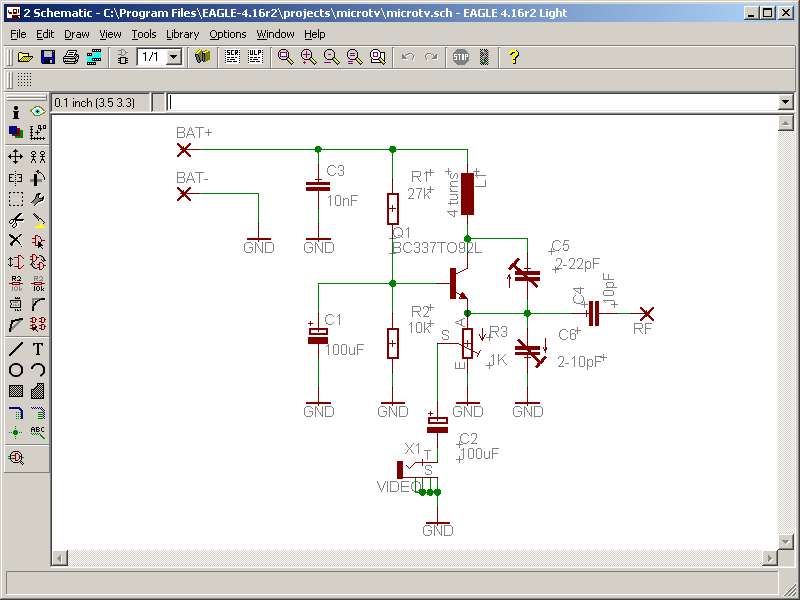
| + | Eagle, software to sketch circuits: | ||
| + | |||
| + | [[File:Eagle.png|800px]] | ||
| + | |||
| + | |||
| + | Video about the basics of etching: | ||
| + | |||
| + | https://www.youtube.com/watch?v=tWnfnt2rNO0 | ||
| + | |||
| + | |||
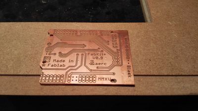
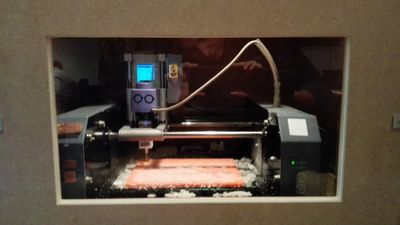
| + | I was at Fablab Amsterdam where a milling machine for PCB's was: | ||
| + | |||
| + | [[File:IMG 20151105 173008.jpg|400px]] [[File:IMG 20151105 173027.jpg|400px]] | ||
| + | |||
| + | |||
| + | == WEEK #6 ETCHING == | ||
| + | |||
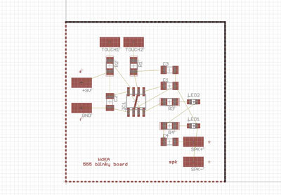
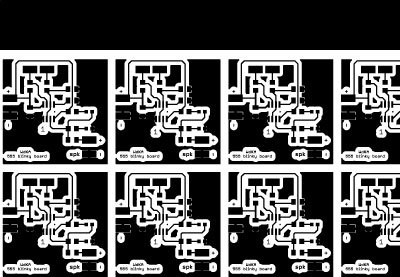
| + | During the class we made step for step a 555 led blinker circuit in Eagle.<br> | ||
| + | Then we printed the circuit on copper and started etching. | ||
| + | |||
| + | [[File:Eagle01.jpg|400px]] [[File:Eagle02.jpg|400px]] | ||
| + | |||
| + | == WEEK #7 ETCHING == | ||
| + | |||
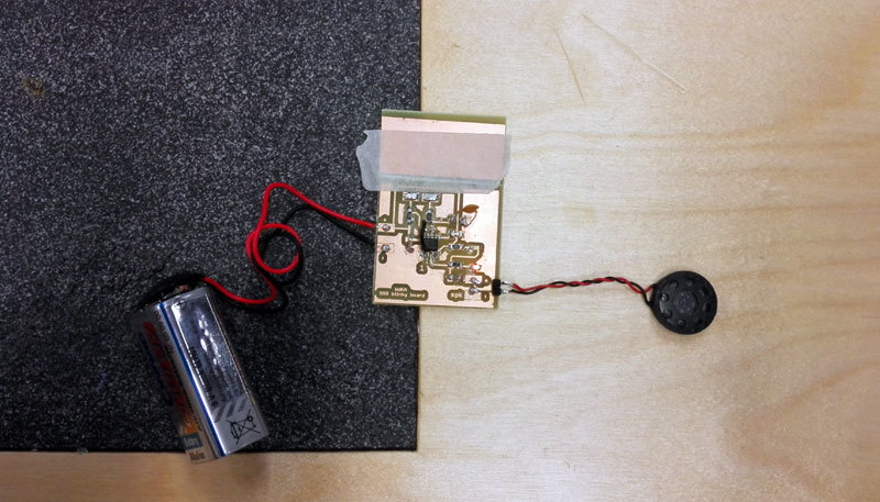
| + | Soldering our own 555 led blinker circuit.<br> | ||
| + | Step 1 is to connect all the elements to the circuit to get noise out of the speakers when you touch the touch-plates: | ||
| + | |||
| + | [[File:Step01.jpg|800px]] | ||
| + | |||
| + | |||
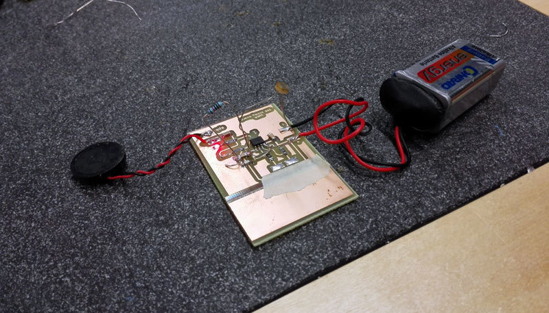
| + | Step 2 is to add a resistor and a light sensor to change the sound: | ||
| + | |||
| + | [[File:Step02.jpg|800px]] | ||
| + | |||
| + | |||
| + | == WEEK #8 ARDUINO AND PIR SENSOR == | ||
| + | |||
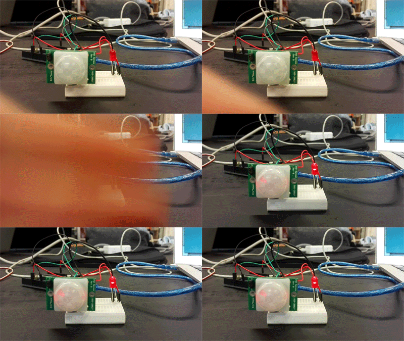
| + | Working with the arduino, PIR sensor (motion sensor), a led light and a servo motor:<br> | ||
| + | [[Joeke Prototype Sensor 15 16 | (For full project page click here)]] | ||
| + | |||
| + | [[File:Servo slow.gif|400px]] [[File:Pir led small.gif|400px]] | ||
| + | |||
| + | |||
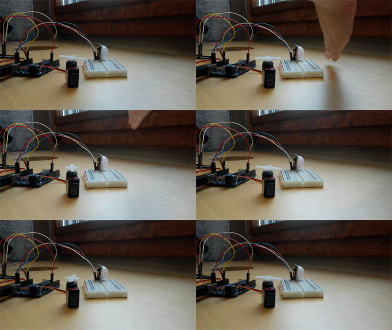
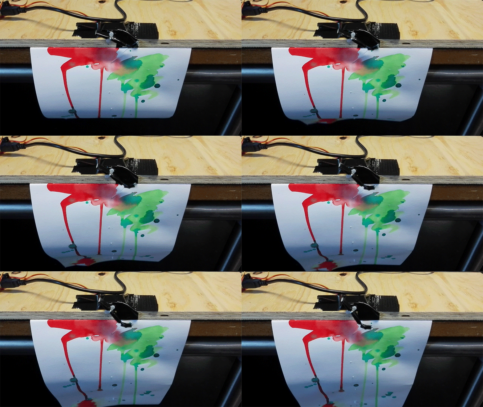
| + | Making a prototype from an interactive, living poster for a Bio Design exhibition: | ||
| + | |||
| + | [[File:Pir bioposter.gif|800px]] | ||
Latest revision as of 10:31, 24 November 2015
Contents
Week #1 Measuring Resistance
Measuring the resistance of different materials:
Week #2 Reading Assignment
Simon absent, reading assignment about resistors and circuits. Notes:
Resistor color code:
Basic circuit and the Ohms Law:
Week #3 Take Apart Electronic Device
Take apart an electric razor to discover the different parts inside of the device, and how the circuit works:
Interesting parts: led light and rotating motor:
Week #4 Building a Circuit
Trying to build a circuit for a speaker:
Week #5 Inspiration For Making Circuits
Discussing different ways to make circuits.
Examples of etching and circuit installations by Peter Vogel:
Eagle, software to sketch circuits:
Video about the basics of etching:
https://www.youtube.com/watch?v=tWnfnt2rNO0
I was at Fablab Amsterdam where a milling machine for PCB's was:
WEEK #6 ETCHING
During the class we made step for step a 555 led blinker circuit in Eagle.
Then we printed the circuit on copper and started etching.
WEEK #7 ETCHING
Soldering our own 555 led blinker circuit.
Step 1 is to connect all the elements to the circuit to get noise out of the speakers when you touch the touch-plates:
Step 2 is to add a resistor and a light sensor to change the sound:
WEEK #8 ARDUINO AND PIR SENSOR
Working with the arduino, PIR sensor (motion sensor), a led light and a servo motor:
(For full project page click here)
Making a prototype from an interactive, living poster for a Bio Design exhibition:
