Difference between revisions of "User:Dionne/Process Tools of the Trade"
| (71 intermediate revisions by the same user not shown) | |||
| Line 83: | Line 83: | ||
wires embedded within. Kong picked the best shapes in terms of ergonomics and in terms of electrical sensitivity. <br> | wires embedded within. Kong picked the best shapes in terms of ergonomics and in terms of electrical sensitivity. <br> | ||
| − | == '''RESEARCH''' == | + | == '''RESEARCH DOCUMENT''' == |
[[User:Dionne Research Tools of the Trade]] | [[User:Dionne Research Tools of the Trade]] | ||
| Line 118: | Line 118: | ||
[[File:Tools of the Trade concept17.jpg | 900px]] | [[File:Tools of the Trade concept17.jpg | 900px]] | ||
Instructions of what the outcome would be while using these objects. With a base of five black strokes. | Instructions of what the outcome would be while using these objects. With a base of five black strokes. | ||
| + | |||
| + | [image] | ||
| + | I tried to laser cut the foam, to get more smooth lines. Because there weren't any default settings for this material | ||
| + | and this thickness I had to try it out with different settings a few times. | ||
== '''SINTERKLAAS SURPRISE''' == | == '''SINTERKLAAS SURPRISE''' == | ||
| Line 134: | Line 138: | ||
products do not speak for themselves yet, and the shapes aren't interesting and exciting enough. The material though | products do not speak for themselves yet, and the shapes aren't interesting and exciting enough. The material though | ||
is nice, because she got triggered to touch them and play with them, and that is exactly what I wanted her to do. So I | is nice, because she got triggered to touch them and play with them, and that is exactly what I wanted her to do. So I | ||
| − | know I have to work on the design now, but of course the technical side as well. | + | know I have to work on the design now, but of course the technical side as well.<br> |
| + | [[File:Denise-sinterklaas surprise digital craft.png | 400 px]] | ||
'''Plan of action''' | '''Plan of action''' | ||
| Line 147: | Line 152: | ||
== '''PROCESSING''' == | == '''PROCESSING''' == | ||
| + | |||
| + | === '''BASICS''' === | ||
| + | () = parameters | ||
| + | syntax = de formule van de code | ||
| + | size canvas = '''size(x,y);''' | ||
| + | smooth = '''smooth();''' ?? | ||
| + | add color = RGB (red, green, blue) | ||
| + | greyscale = 0 tot 255 (0) = black, (255) = white | ||
| + | background = '''background(R,G,B);''' | ||
| + | stroke = outline '''stroke(R,G,B);''' | ||
| + | fill = interior '''fill(R,G,B);''' | ||
| + | // ..... = text line in the code | ||
| + | rect = '''rect(x,y,width,height);''' | ||
| + | ellipse = '''ellipse(x,y,width,height);''' | ||
| + | order = the 2nd code line is on top of the first code line and so on | ||
| + | arc = section of an ellipse '''arc(x, y, width, height, start, stop);''' | ||
| + | spline curve = '''curve(cpx1, cpy1, x1, y1, x2, y2, cpx2, cpy2);''' | ||
| + | control point = cp | ||
| + | continuous spline curve = '''beginShape(); curveVertex(); endShape();''' | ||
| + | bezier curve = '''bezier(x1, y1, cpx1, cpy1, cpx2, cpy2, x2, y2);''' | ||
| + | continuous bezier curve = '''bezierVertex(cpx1, cpy1, cpx2, cpy2, x, y);''' | ||
| + | |||
| + | * '''Use arc()''' when you need a segment of a circle or an ellipse. You can’t make continuous arcs or use them as part of a shape. | ||
| + | * '''Use curve()''' when you need a small curve between two points. Use curveVertex() to make a continuous series of curves as part of a shape. | ||
| + | * '''Use bezier()''' when you need long, smooth curves. Use bezierVertex() to make a continuous series of Bézier curves as part of a shape. | ||
| + | |||
| + | |||
| + | At [https://processing.org processing.org] I learned the basics of processing by a nice tutorial from Daniel Shiffman step by step: | ||
| + | |||
| + | '''1: SHAPE''' | ||
| + | Draw a picture made of ellipses and rectangles! | ||
| + | '''Reminders:''' | ||
| + | To draw a rectangle: rect(a,b,c,d); | ||
| + | To draw an ellipse: ellipse(a,b,c,d); | ||
| + | a — X (horizontal) location of the shape's upper-left corner | ||
| + | b — Y (vertical) location of the shape's upper-left corner | ||
| + | c — width of the shape | ||
| + | d — height of the shape | ||
| + | |||
| + | [[File:Processing tutorial 3.png | 600px]] | ||
| + | |||
| + | '''2: COLOR''' | ||
| + | Add color to your design! | ||
| + | '''Reminders:''' | ||
| + | Set the background color: background(r,g,b); | ||
| + | Set the outline color: stroke(r,g,b); | ||
| + | Set the interior color: fill(r,g,b); | ||
| + | |||
| + | Don't forget, you need to call stroke() and fill() before you draw the shape! | ||
| + | R — amount of red, from 0 (none) to 255 (maximum) | ||
| + | G — amount of green, from 0 (none) to 255 (maximum) | ||
| + | B — amount of blue, from 0 (none) to 255 (maximum) | ||
| + | |||
| + | [[File:Processing tutorial 4.png | 600px]] | ||
| + | |||
| + | '''3: INTERACT''' | ||
| + | Animate your program using mouseX and mouseY! | ||
| + | '''Syntax for setup() and draw(), here is a reminder:''' | ||
| + | void setup() { | ||
| + | size(500,400); | ||
| + | } <br> | ||
| + | void draw() { | ||
| + | background(0,0,0); | ||
| + | fill(255,255,255); | ||
| + | ellipse(mouseX,mouseY,60,60); | ||
| + | } <br> | ||
| + | We recommend a maximum canvas size of 500 by 400 pixels for this tutorial. | ||
| + | |||
| + | [[File:Processing tutorial 6.png | 600px]] | ||
| + | |||
| + | '''4: QUESTIONS''' | ||
| + | Use a mouse press to change what your program is doing! | ||
| + | Here is an example of drawing a different color depending on whether the mouse is pressed. | ||
| + | void setup() { | ||
| + | size(500,400); | ||
| + | } <br> | ||
| + | void draw() { | ||
| + | background(0); | ||
| + | if (mousePressed) { | ||
| + | fill(0,255,0); | ||
| + | } else { | ||
| + | fill(255,0,0); | ||
| + | } | ||
| + | ellipse(mouseX,mouseY,60,60); | ||
| + | }<br> | ||
| + | You could also consider drawing the background only when the mouse is pressed. For example: | ||
| + | void setup() { | ||
| + | size(500,400); | ||
| + | background(0); | ||
| + | } <br> | ||
| + | void draw() { | ||
| + | if (mousePressed) { | ||
| + | background(0); | ||
| + | } | ||
| + | ellipse(mouseX,mouseY,60,60); | ||
| + | } <br> | ||
| + | When I clicked on the canvas the blue shapes appeared, when I didn't clicked the red shapes appeared. | ||
| + | [[File:Processing tutorial 8.png | 600px]] | ||
| + | [[File:Processing tutorial 9.png | 600px]] | ||
| + | |||
| + | '''SAVE PRINT''' | ||
| + | I also want to know how to export the print to an image, because then it can be used as a digital print. It goes like this: | ||
| + | [[File:Save in processing.png | 700px]] | ||
| + | Simon helped me with this, and put it in the code, so when the mouse is pressed it saves the file as a PNG. Example: | ||
| + | [[File:Processing.png | 500px]] | ||
| + | Outcome Example: | ||
| + | [[File:Save testje png.png |500px]] | ||
| + | |||
| + | ==='''SHAPES'''=== | ||
| + | |||
| + | I managed to make the first simple basic shapes, although for me they weren't that easy to figure out. | ||
| + | With the drawings I made before in my mind I start to experiment with the shape of multiple lines on a canvas. | ||
| + | I did the Pull, Bend, Curve and Tilt functions. Wherever your mouse goes it starts to Pull, Bend Curve or Tilt. | ||
| + | |||
| + | [[File:Processing pull.png | 500px]] [[File:Processing curve.png | 500px]] | ||
| + | |||
| + | [[File:Processing-Bend.png | 500px]] [[File:Processing-Tilt.png |500px]] | ||
| + | |||
| + | I've made a GIF to show how the shapes move. | ||
| + | [[File:UgFNNg.gif |300px]] [[File:S2TPOU.gif |400px]] | ||
| + | [[File:UnbizT.gif |300px]] [[File:9IGDU-.gif | 300px]] | ||
| + | |||
| + | ==='''CODE'''=== | ||
| + | |||
| + | [[File:Processing serialBend 1.png | 900px]]<br> | ||
| + | [[File:Processing serialBend 2.png |900px]]<br> | ||
| + | This is the code I used which is connected to the arduino and the sensors flex, force and light. | ||
== '''SENSORS''' == | == '''SENSORS''' == | ||
| + | |||
| + | Because I am going to experiment with sensors I decided to buy the '''Essential Sensor Kit''' from [https://www.antratek.nl Antratek.nl] | ||
| + | |||
| + | [[File:Kit-sensor-1.png |800 px]] | ||
| + | [[File:Kit-sensor-2.png |500px]] | ||
| + | [[File:Kit-sensor-3.png |300px] | ||
| + | |||
| + | == '''ARDUINO''' == | ||
| + | |||
| + | [[File:Arduino serialBend.png | 800px]]<br> | ||
| + | This is the code I used to connect the sensors to the computer, I can connect the flex, force or light sensor on. | ||
Latest revision as of 20:39, 24 January 2016
Contents
THEME TACTILITY
• Sensory ability

• E-textiles

• stimulates the sense to touch

• makes the fabric come to life

• interact with the user*

• Playful three dimensional effect

• Tactile experience

* You can only fully experience the fabric by touching it
The theme that I am going to work with for the tools & trade project is: tactility.
In combination with the craft textile surface design.
The surfaces that I want to make have a sensory ability and are e-textiles.
They stimulate the sense to touch and it makes the fabric come to life.
It wil interact with the user, because you can only fully experience the fabric by touching it.
It will have a playful three dimensional effect which will give a tactile experience.
• An escape from your digitized everyday life*

• To reconnect with people in your surroundings

• Ability to change & adapt to our fast fashion industry

• Gives a new textile experience

*A respond to our contemporary society’s digitization
A few scenarios that exist while using these surfaces are the following:
It is an escape from your digitized everyday life and daily rituals.
This surface is a respond to our contemporary society’s digitization.
It will help you to reconnect with people in your surroundings, because you can experience it with more then one persons.
This surface has the ability to change & adapt to our fast fashion industry without having to throw it away immedieatly, this can be used for a longer period of time.
All together this will give you a new textile experience.
• Craft: Designing prints and patterns for textiles through the digital software Adobe Illustrator.

• Problem: The physical experience between the user and the computer is very limited. There is not much interaction with the software
  other then clicks and swipes on a trackpad, mouse or pen.

• Tool(Kit): A tangible visualization of enhanced Illustrator tools that are physically exiting and triggers the sense to touch.
  It creates a relation of the physical interface between humans and computers.

• Goal: The tools exist out of ergonomic responsible shapes and materials, and are comfortable to work with. They respond on the
  software Illustrator and create new possibilities and results in the field of Textile Print Design.

• Software: The Illustrator tools are redefined and enhanced. The tools are responsive through capacitive touch and motion sensors.

• Research: To the existence of the trackpad/mouse/tablet/pen etc. To understand why and how they are made the way they are today.

• Statement: Write a good statement why this is useful for me and others and why this should change.
INSPIRATION
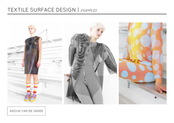
Graduated from the Design Academy Eindhoven with Print in Motion garments.

They produce visual effects as the wearer moves.

This is called the moiré effect.

Although this is more about motion instead of touch, I like that her approach make the prints come to life.
Is an augmented modeling tool that lets you design 3d printed wearables directly on your body.

It uses depth sensing and projection mapping to detect and display touch gestures on the skin.

Every design is ready to be 3d printed and worn back on the body.

This project makes 3d printing accessible for the user and stimulates your touch senses.
Designed 'Tactile Dialogues' which is a textile object in the form of a pillow with integrated vibration elements that react on touch.

Their goal is to trigger physical communication patterns between a person with severe dementia and a family member.

What I like about this project is that it let the user reconnect with people they're surrounded with.
As a result of the dominance of visual and digital information in design, the surface qualities of our

immediate surroundings are often disregarded.

She says 'We live in a polished environment with little focus on haptic experiences'.

The diversity of tactile stimuli in nature is significantly larger than in our artificial surroundings.

With her project she questioned 'Why couldn't man made objects offer, similarly stimulating experiences?'.

She times to translate natures qualities into interior surfaces.
Marie Rouillon: Questions how can material experiences reconnect people with tactility in our digitised lives? The interactions that we

entertain with everyday devices are lacking sensibility, tactility and sensory experiences. As a textile designer, Rouillon is

particularly interested in what we call the sense(s) of touch. Daily Haptics has emerged as a response to this insight, through her

design, she is creating tactile experiences in order to reconnect people with tactility. Comprised of cups that look the same but feel

different, this series responds to contemporary society’s digitization and aims to re-engage people with tactile, material experiences.

Visual information alone is not enough, one needs to touch it to get full information. ‘I took the decision to communicate my

concept through everyday objects, without digital tools, in order to stress even more this urge to touch and experience the

everyday world we live in, through multi-sensory experiences.’
Royal College of Art graduate Ming Kong has created an elastic  conductive material that can be moulded into different shapes, and to

create a haptic interface for manipulating digital models and files. Kong was frustrated with designing interfaces for electronics

products using only flat buttons, so decided to create three-dimensional tools for navigating digital environments. To do this, he

developed a conductive silicon-based material that can sense touch and directional movement across its surface, without sensors or

wires embedded within. Kong picked the best shapes in terms of ergonomics and in terms of electrical sensitivity.
RESEARCH DOCUMENT
User:Dionne Research Tools of the Trade
MATERIAL EXPERIMENTS
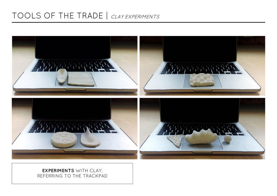
CLAY
For the first experiments I took clay as a material to see which kind of shapes and forms I can make with my hand.
With the Illustrator tools in mind I created a visualization. Although the outcome is very tangible, it is very stiff and
has a hard surface. This will restrict the playful effect and fully experience the function of each tool.
So clay is not the best material to work with, it gets hard and then it will break. I need a material that is flexible and
elastic, which you can stretch out of proportion but when letting go of it, it'll return to it's original shape.
Maybe silicone will work better.
POLYURETHANE FOAM
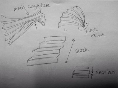
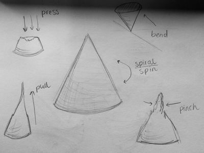
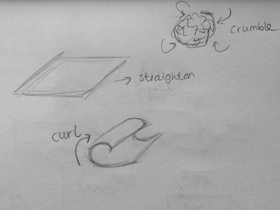
Sketches I made for my second material experiment. With these I try to redefine hand gestures
we can make, and make these gestures useful in the objects, such as, pulling, pinching, pressing,
crumbling etc.
With this experiment I searched for a material that responds on touch. A material where you can press, pinch
and pull on. That's why I started experimenting with polyurethane foam. I bought two pieces from the market in
Rotterdam and started cutting, folding and gluing it together. As a reference to the sketches I made.
The end result are these crazy forms, that triggers you to touch and are also pleasant to touch. Only the parts
where it is glued it became a hard surface. I've made some instructions so you can see how to use them.
Now I want to find out if I can make my own foam out of malls. But first I will start sketching more specifically.

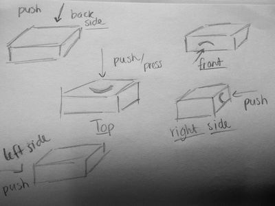
Instructions of how to use the little objects.

Instructions of what the outcome would be while using these objects. With a base of five black strokes.
[image]
I tried to laser cut the foam, to get more smooth lines. Because there weren't any default settings for this material
and this thickness I had to try it out with different settings a few times.
SINTERKLAAS SURPRISE
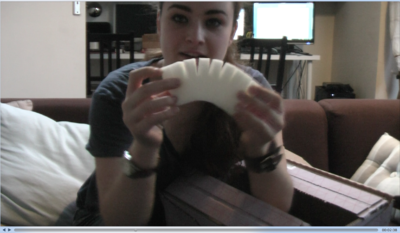
Denise had to unbox my sinterklaas surprise and record it on the webcam.
I gave her a box with all the above objects in it without any explanation.
At first she didn't know what to do with these little objects. She started to feel them in different ways and tried
to come up with the purpose of it. Also she gave good feedback. The triangle, cirkel and square shapes she found
less interesting and simple and would not inspire her or encourage her. Although the more difficult shapes she found
inspiring and triggering and she was interested in the purpose of these. Which was also my intention, because I want to
see how far I can go with this material. She also said go crazy with them and leave the simple objects out. Then she said
maybe these are something to paint or brush with, or weave with. So she came close..  And then with   one object
she said, maybe this is a computer mouse.. So now she was coming very close to its purpose. She played a lot with
the shapes and discovered new forms by pulling, pushing, bending etc. of the objects. She also started to build
them on top of each other to see wether it was a construction of loose pieces.  She gave me lots to think about, the
products do not speak for themselves yet, and the shapes aren't interesting  and exciting enough. The material though
is nice, because she got triggered to touch them and play with them, and that is exactly what I wanted her to do. So I
know I have to work on the design now, but of course the technical side as well.
Plan of action
So what's next?

Step 1: Concept (A tool that makes print through a tangible but digital way)
Step 2: Sketches (Different shapes and sizes)
Step 3: Experiments (Clay, Foam, Laser Cut, Glue)
Step 4: Processing (Try outs with mouse)
Step 5: Sensors / Aurdino (Make the technical parts)
Step 6: Building the foam device (Build the technical parts in the foam)
Step 7: Building the connection to the laptop (USB)
PROCESSING
BASICS
() = parameters
syntax = de formule van de code
size canvas = size(x,y);
smooth =  smooth(); ??
add color = RGB (red, green, blue)
greyscale = 0 tot 255 (0) = black, (255) = white
background = background(R,G,B);
stroke = outline stroke(R,G,B);
fill = interior fill(R,G,B);
// ..... = text line in the code
rect = rect(x,y,width,height);
ellipse = ellipse(x,y,width,height);
order = the 2nd code line is on top of the first code line and so on
arc = section of an ellipse arc(x, y, width, height, start, stop);
spline curve = curve(cpx1, cpy1, x1, y1, x2, y2, cpx2, cpy2);
control point = cp
continuous spline curve = beginShape(); curveVertex(); endShape();
bezier curve =  bezier(x1, y1, cpx1, cpy1, cpx2, cpy2, x2, y2);
continuous bezier curve = bezierVertex(cpx1, cpy1, cpx2, cpy2, x, y);
- Use arc() when you need a segment of a circle or an ellipse. You can’t make continuous arcs or use them as part of a shape.
- Use curve() when you need a small curve between two points. Use curveVertex() to make a continuous series of curves as part of a shape.
- Use bezier() when you need long, smooth curves. Use bezierVertex() to make a continuous series of Bézier curves as part of a shape.
At processing.org I learned the basics of processing by a nice tutorial from Daniel Shiffman step by step:
1: SHAPE
Draw a picture made of ellipses and rectangles!
Reminders:
To draw a rectangle: rect(a,b,c,d);
To draw an ellipse: ellipse(a,b,c,d);
a — X (horizontal) location of the shape's upper-left corner
b — Y (vertical) location of the shape's upper-left corner
c — width of the shape
d — height of the shape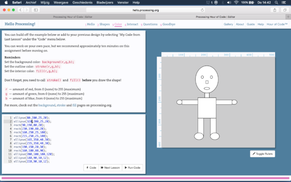
2: COLOR
Add color to your design!
Reminders:
Set the background color: background(r,g,b);
Set the outline color: stroke(r,g,b);
Set the interior color: fill(r,g,b);

Don't forget, you need to call stroke() and fill() before you draw the shape!
R — amount of red, from 0 (none) to 255 (maximum)
G — amount of green, from 0 (none) to 255 (maximum)
B — amount of blue, from 0 (none) to 255 (maximum)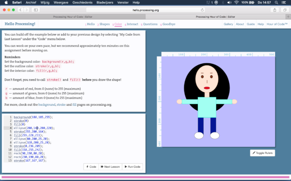
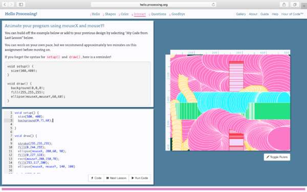
3: INTERACT
Animate your program using mouseX and mouseY!
Syntax for setup() and draw(), here is a reminder:
void setup() {
  size(500,400);
}

 void draw() {
 background(0,0,0);
 fill(255,255,255);
 ellipse(mouseX,mouseY,60,60);
}

We recommend a maximum canvas size of 500 by 400 pixels for this tutorial.
4: QUESTIONS
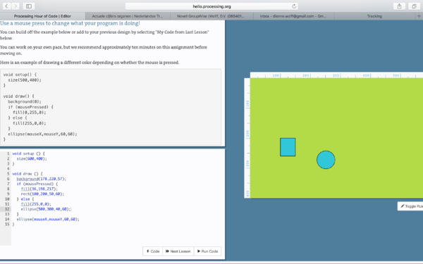
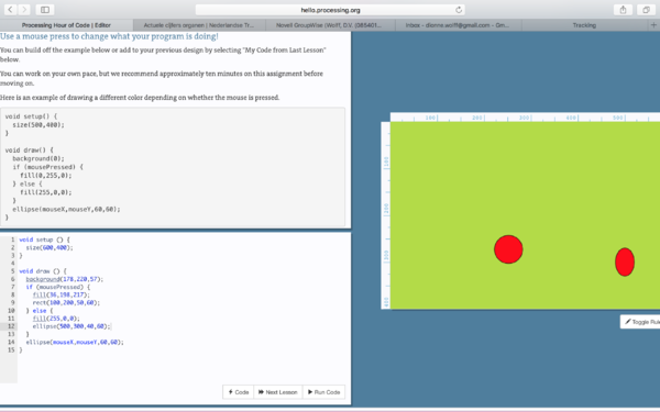
Use a mouse press to change what your program is doing!
Here is an example of drawing a different color depending on whether the mouse is pressed.
void setup() {
 size(500,400);
}

void draw() {
 background(0);
 if (mousePressed) {
   fill(0,255,0);
 } else {
   fill(255,0,0);
 }
  ellipse(mouseX,mouseY,60,60);
 }

You could also consider drawing the background only when the mouse is pressed. For example:
void setup() {
 size(500,400);
 background(0);
}

void draw() {
 if (mousePressed) {
   background(0);
}
  ellipse(mouseX,mouseY,60,60);
}

When I clicked on the canvas the blue shapes appeared, when I didn't clicked the red shapes appeared.
SAVE PRINT I also want to know how to export the print to an image, because then it can be used as a digital print. It goes like this:Simon helped me with this, and put it in the code, so when the mouse is pressed it saves the file as a PNG. Example:
Outcome Example:

SHAPES
I managed to make the first simple basic shapes, although for me they weren't that easy to figure out. With the drawings I made before in my mind I start to experiment with the shape of multiple lines on a canvas. I did the Pull, Bend, Curve and Tilt functions. Wherever your mouse goes it starts to Pull, Bend Curve or Tilt.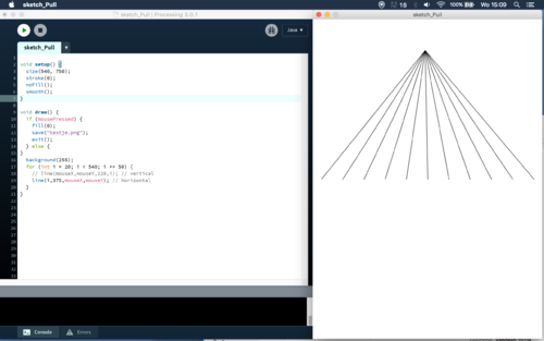
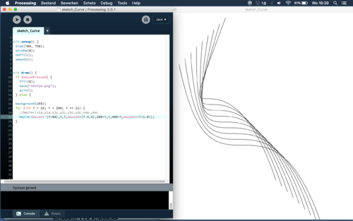
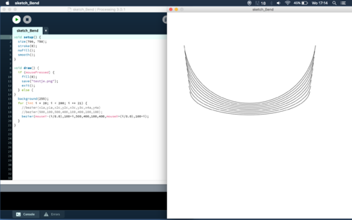
I've made a GIF to show how the shapes move.


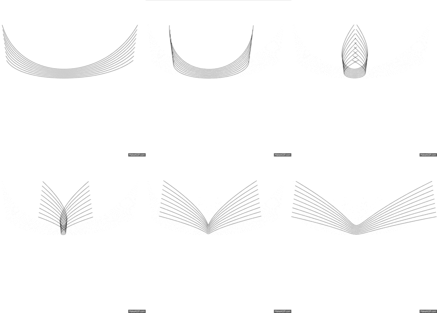
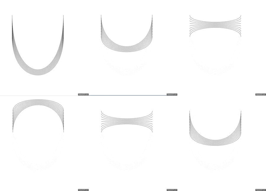
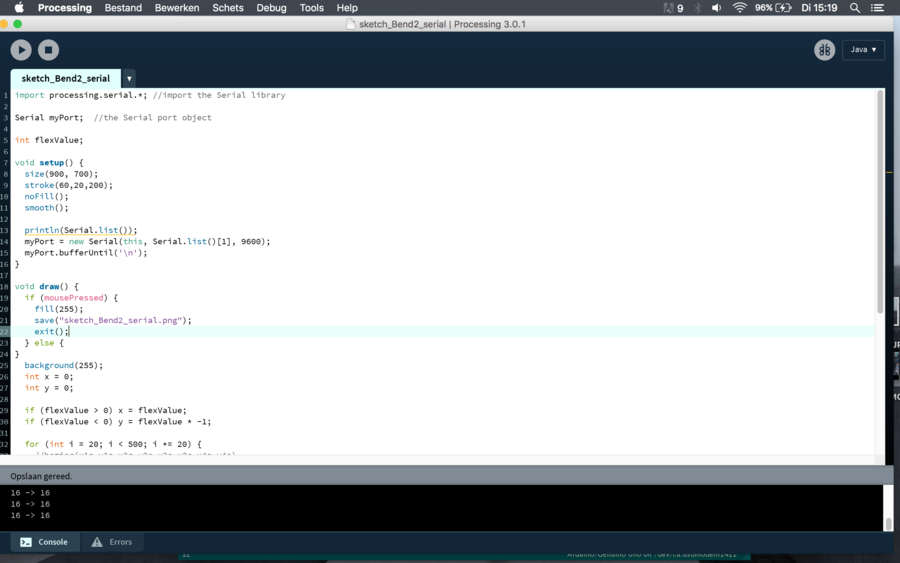
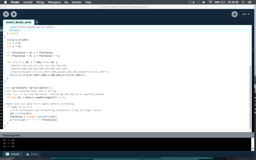
CODE
This is the code I used which is connected to the arduino and the sensors flex, force and light.
SENSORS
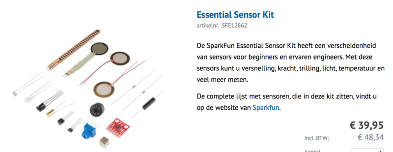
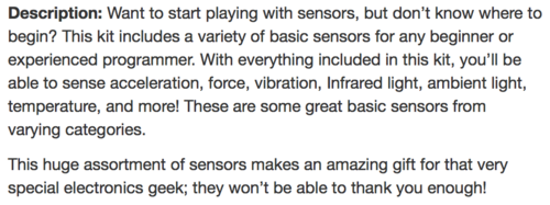
Because I am going to experiment with sensors I decided to buy the Essential Sensor Kit from Antratek.nl
 [[File:Kit-sensor-3.png |300px]
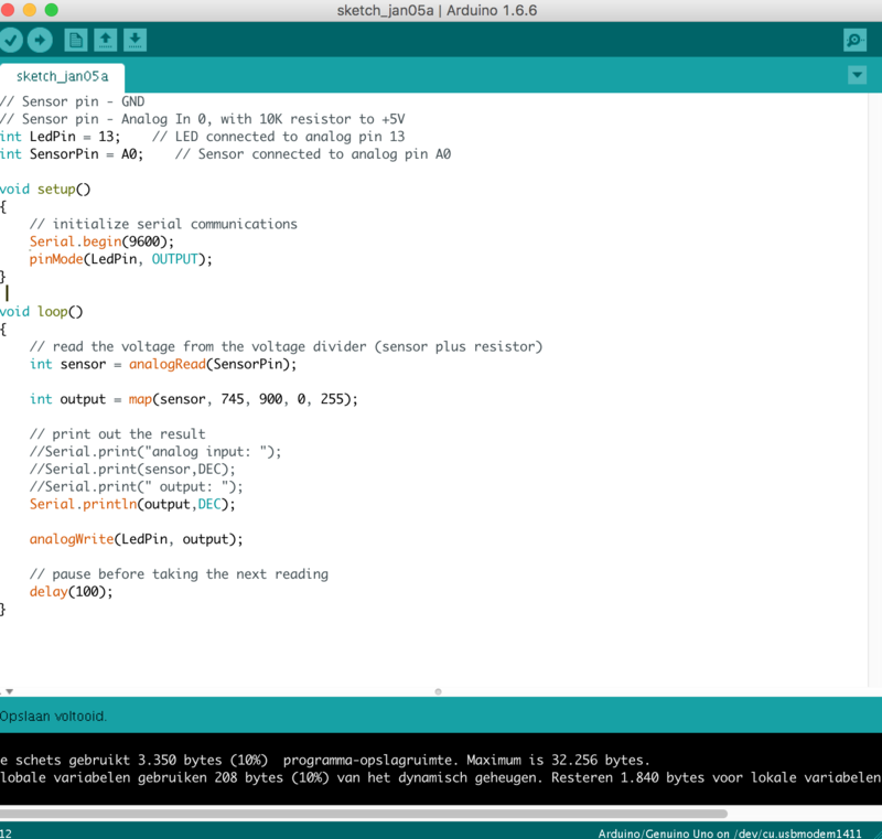
ARDUINO
This is the code I used to connect the sensors to the computer, I can connect the flex, force or light sensor on.
