Difference between revisions of "PracticalTheExpandedToolbox/Lab3"
Dennisdebel (talk | contribs) |
Dennisdebel (talk | contribs) |
||
| Line 24: | Line 24: | ||
== Datasheets == | == Datasheets == | ||
| + | All electronic components come with a datasheet. This is like the service manual of the component. For example IC's or Integrated Circuits are (complex) electronics circuits build into a tiny (often black) package. The datasheet will reveal the function of these 'black boxes'. Among others, datasheets can tell you: | ||
| + | |||
| + | * Specs: how much voltage does this component need? how much current does it draw? | ||
| + | * Pin-out's: where to connect what to? | ||
| + | * Example applications: example schematics for different functions/uses of the chip | ||
| + | * Footprint: measurements for making schematics etc, how big is the physical object? | ||
| + | |||
| + | The datasheet for the '555' IC we will be using can be found here: [[Media:Na555.pdf]] | ||
| + | |||
== BOM == | == BOM == | ||
BOM or Bill Of Materials is common engineering language for list of components you need to build something. | BOM or Bill Of Materials is common engineering language for list of components you need to build something. | ||
Revision as of 17:59, 17 May 2017
Contents
Introduction
Circuits can be made in many different ways:
- prototype board (e.g. perfboard or stripboard)[5]
- volumetric circuits[6][7]
- Etching a Printed Circuit Board (PCB)[8][9].
There are still other ways of making circuits, for example using the vinyl cutter to cut copper traces, using conductive fabric, etc. A nice overview of other alternative methods you can find at the great website of KobaKant: How To Get What You Want. Besides a lot of other interesting stuff (browse through it!!) the traces making sections you can find here: Kobakant section on Traces.
It is even possible to (almost) entirely knit your circuit: The Knitted Radio, Drapery FM.
In this lab you will be making a circuit with your preferred method with exception of the breadboard. The circuit presented here is a touch sensitive noise making circuit.
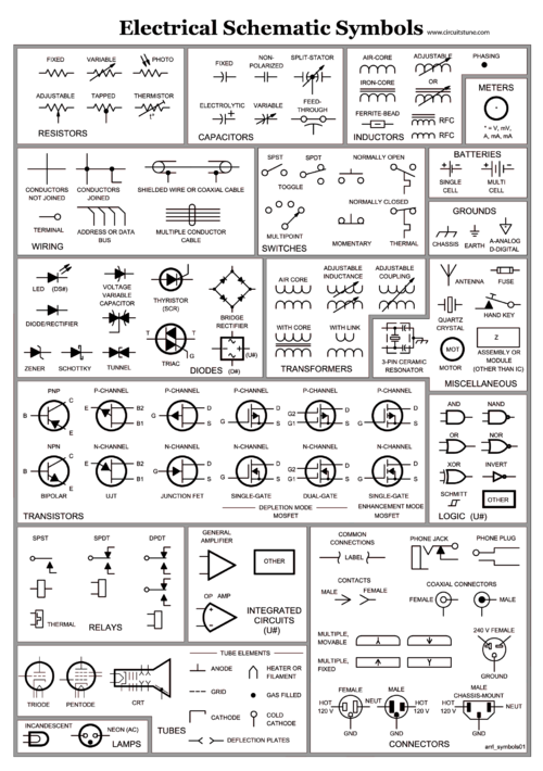
Symbols
During first class you received a leaflet with symbols used schematics of electronic circuits and their meaning. You will need this to decipher the schematic below. Here you find a copy of an american version (notice the resistor symbols):
Datasheets
All electronic components come with a datasheet. This is like the service manual of the component. For example IC's or Integrated Circuits are (complex) electronics circuits build into a tiny (often black) package. The datasheet will reveal the function of these 'black boxes'. Among others, datasheets can tell you:
- Specs: how much voltage does this component need? how much current does it draw?
- Pin-out's: where to connect what to?
- Example applications: example schematics for different functions/uses of the chip
- Footprint: measurements for making schematics etc, how big is the physical object?
The datasheet for the '555' IC we will be using can be found here: Media:Na555.pdf
BOM
BOM or Bill Of Materials is common engineering language for list of components you need to build something. Our current BOM:
| Component | Label on schematic and board layout | Value | Has polarity (does the part orientation matter?) |
|---|---|---|---|
| IC | 555 | NE555 | Yes |
| Resistor | R1 | 220k (224) | No |
| Resistor | R2 | 10k (103) | No |
| Resistor | R3, R4 | 1k (102) | No |
| Resistor | R6 | 0R (0) | No |
| Resistor | R5, R7 | Do not mount (yet) | No |
| Capacitor | C1 | 10uF (dark brown) | No |
| Capacitor | C2 | 0.1uF (micro Fahrad) (brown) | No |
| Capacitor | C3 | 1nF (nano Fahrad) (light grey) | No |
| LED | Led1, Led2 | - | Yes (green dot (cathode) points down towards board edge) |
| 9V Battery Clip | VCC | - | Yes |
| Speaker | SPK | 8 Ohm - 16 Ohm | No |
Schematics
Stencils
Soldering
Assignment
- Form duo's
- Collect all the parts of the BOM (get a helping hand)
- Download the NE555 datasheet, read it.
- Choose a schematic
- Choose a desired method to make the circuit and make it (work)!
- Watch the polarity of components! Prevent short circuits, 'solder bridges', good luck!
Don't hesitate to try out different resistor values!
Demo of example board: https://www.youtube.com/watch?v=sOlpj5MdCnk
