Difference between revisions of "PracticalTheExpandedToolbox/Lab3"
Dennisdebel (talk | contribs) (→NE555) |
Dennisdebel (talk | contribs) |
||
| Line 41: | Line 41: | ||
* SMD components have legs you solder on top of the PCB. Hence you do not need to drill any holes. This method of mounting components is the standard way these days as components can be much smaller and fabrication is cheaper (less drilling and plating of holes). Many more advanced components only come in SMD packages so it is a valuable skill to be able to work with and solder these components. However, as SMD components are usually meant to be mounted by machines, some are difficult or too small to handle with human hands, so when looking for components be sure to carefully check which package you select. A good overview of package types, sizes and names can be found on Wikipedia: https://en.wikipedia.org/wiki/Surface-mount_technology#Packages | * SMD components have legs you solder on top of the PCB. Hence you do not need to drill any holes. This method of mounting components is the standard way these days as components can be much smaller and fabrication is cheaper (less drilling and plating of holes). Many more advanced components only come in SMD packages so it is a valuable skill to be able to work with and solder these components. However, as SMD components are usually meant to be mounted by machines, some are difficult or too small to handle with human hands, so when looking for components be sure to carefully check which package you select. A good overview of package types, sizes and names can be found on Wikipedia: https://en.wikipedia.org/wiki/Surface-mount_technology#Packages | ||
<br/> | <br/> | ||
| + | |||
| + | In this Lab we will mix both! | ||
=== NE555 === | === NE555 === | ||
| Line 82: | Line 84: | ||
The capacitors we use are all of the ceramic type and do not have a polarity. | The capacitors we use are all of the ceramic type and do not have a polarity. | ||
<br/> | <br/> | ||
| − | |||
== BOM == | == BOM == | ||
Revision as of 18:08, 17 May 2017
Contents
Introduction
Circuits can be made in many different ways:
- prototype board (e.g. perfboard or stripboard)[5]
- volumetric circuits[6][7]
- Etching a Printed Circuit Board (PCB)[8][9].
There are still other ways of making circuits, for example using the vinyl cutter to cut copper traces, using conductive fabric, etc. A nice overview of other alternative methods you can find at the great website of KobaKant: How To Get What You Want. Besides a lot of other interesting stuff (browse through it!!) the traces making sections you can find here: Kobakant section on Traces.
It is even possible to (almost) entirely knit your circuit: The Knitted Radio, Drapery FM.
In this lab you will be making a circuit with your preferred method with exception of the breadboard. The circuit presented here is a touch sensitive noise making circuit.
Symbols
During first class you received a leaflet with symbols used schematics of electronic circuits and their meaning. You will need this to decipher the schematic below. Here you find a copy of an american version (notice the resistor symbols):

Datasheets
All electronic components come with a datasheet. This is like the service manual of the component. For example IC's or Integrated Circuits are (complex) electronics circuits build into a tiny (often black) package. The datasheet will reveal the function of these 'black boxes'. Among others, datasheets can tell you:
- Specs: how much voltage does this component need? how much current does it draw?
- Pin-out's: where to connect what to?
- Example applications: example schematics for different functions/uses of the chip
- Footprint: measurements for making schematics etc, how big is the physical object?
The datasheet for the '555' IC we will be using can be found here: Media:Na555.pdf
Components
There are two main types of component mounting: DIP[10] (also known as through hole) and SMD[11].
- DIP or through hole components have legs you stick through holes in the PCB. You solder the legs to the bottom (copper) side of the PCB.
- SMD components have legs you solder on top of the PCB. Hence you do not need to drill any holes. This method of mounting components is the standard way these days as components can be much smaller and fabrication is cheaper (less drilling and plating of holes). Many more advanced components only come in SMD packages so it is a valuable skill to be able to work with and solder these components. However, as SMD components are usually meant to be mounted by machines, some are difficult or too small to handle with human hands, so when looking for components be sure to carefully check which package you select. A good overview of package types, sizes and names can be found on Wikipedia: https://en.wikipedia.org/wiki/Surface-mount_technology#Packages
In this Lab we will mix both!
NE555
The NE555, or commonly known as '555 timer' is a very versatile chip or 'IC'. An 'IC' or Integrated Circuit is a (complex) electronic circuit build into a tiny (often black) package. It can be used to create sound (like in this Lab), blink lights, fade lights, turn things on for a short or long time many more. Many things you would want to use e.g. an Arduino for can be solved by this little chip alone or in combination some other circuits resulting in a much smaller and cheaper solution!
The 555 timer chip, like many other chips come in a variety of packages. The most common for this chip are DIP and SOIC. We will use the SOIC version in this lab.
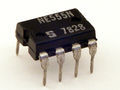
DIP
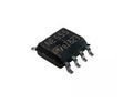
SOIC8 (we will use this one)


Resistor (R)
The resistors we will use are 3216 (1206 imperial) size resistors. This means these are 3.2mm long and 1.6mm wide. There are a variety of sizes available[12]. For hand soldering I would not recommend to smaller than 1608 (0603 imperial) although 1005 (0402 imperial) is still possible with some practice. Anything smaller is only practical for machine assembled boards.
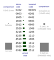
resistor and capacitor sizes
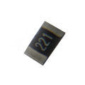
A 3216 size resistor as we used in the lab


The resistors have a marking on them indicating the resistance value in Ohms[13]. The resistors we use have a 3 digit marking: two significant digits and a multiplier. This means you can read the first two digits as you would normaly, the last digit tells you how many zeros to add:
- 220 would mean a 22 and 0 zeros or 22 Ohm
- 221 would mean a 22 and 1 zeros or 220 Ohm
- 222 would mean a 22 and 2 zoros or 2200 Ohm or 2.2 kilo Ohm or 2.2k
- 223 would mean a 22 and 3 zeros or 22000 or 22 kilo Ohm or 22k
- 224 would mean a 22 and 4 zeros or 220000 or 220 kilo Ohm or 220k
- etc.
There is also a special type which is indicated as 0R, this is a zero ohm resistor. It is often used as wire bridge or as placeholder if there may be the possibility a real resistor is needed at some point.
Capacitor (C)
The capacitors have the same sizes as the resistors. However, capacitors have no marking on them. Instead they come in a variety of color shades. This makes them a bit harder to identify. The general rule is the lighter the color and the thinner the capacitor, the lower its value.
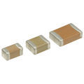
several ceramic SMD capactors

The capacitors we use are all of the ceramic type and do not have a polarity.
BOM
BOM or Bill Of Materials is common engineering language for list of components you need to build something. Our current BOM:
| Component | Label on schematic and board layout | Value | Has polarity (does the part orientation matter?) |
|---|---|---|---|
| IC | 555 | NE555 | Yes |
| Resistor | R1 | 220k (224) | No |
| Resistor | R2 | 10k (103) | No |
| Resistor | R3, R4 | 1k (102) | No |
| Resistor | R6 | 0R (0) | No |
| Resistor | R5, R7 | Do not mount (yet) | No |
| Capacitor | C1 | 10uF (dark brown) | No |
| Capacitor | C2 | 0.1uF (micro Fahrad) (brown) | No |
| Capacitor | C3 | 1nF (nano Fahrad) (light grey) | No |
| LED | Led1, Led2 | - | Yes (green dot (cathode) points down towards board edge) |
| 9V Battery Clip | VCC | - | Yes |
| Speaker | SPK | 8 Ohm - 16 Ohm | No |
Schematics
Stencils
Soldering
Assignment
- Form duo's
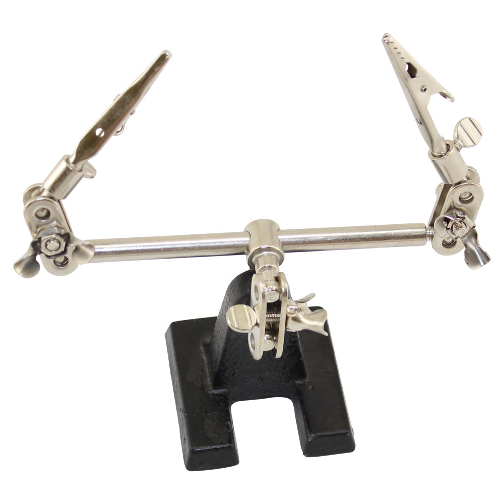
- Collect all the parts of the BOM (get a helping hand)
- Download the NE555 datasheet, read it.
- Choose a schematic
- Choose a desired method to make the circuit and make it (work)!
- Watch the polarity of components! Prevent short circuits, 'solder bridges', good luck!
Don't hesitate to try out different resistor values!
Demo of example board: https://www.youtube.com/watch?v=sOlpj5MdCnk
References
- ↑ Parallax breadboard tutorial
- ↑ Solar Sound Module by Ralf Schreiber
- ↑ Wire wrapping
- ↑ [1]
- ↑ https://en.wikipedia.org/wiki/Perfboard
- ↑ Some examples on Volumetric circuits
- ↑ Peter Vogel, The sound of shadows
- ↑ several etching techniques
- ↑ PCB making, Toner transfer method
- ↑ https://en.wikipedia.org/wiki/Dual_in-line_package
- ↑ https://en.wikipedia.org/wiki/Surface-mount_technology
- ↑ https://en.wikipedia.org/wiki/Surface-mount_technology#Rectangular_passive_components
- ↑ https://en.wikipedia.org/wiki/Surface-mount_technology#Resistors