Difference between revisions of "User:JeroenRijnart/HTBHQ11"
| Line 19: | Line 19: | ||
===Webcam microscope=== | ===Webcam microscope=== | ||
| + | |||
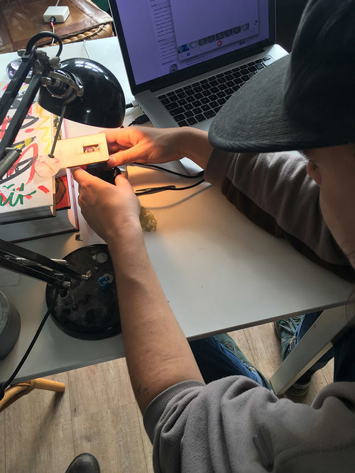
| + | [[File:Filming-objects.JPG | 500px]] | ||
| + | |||
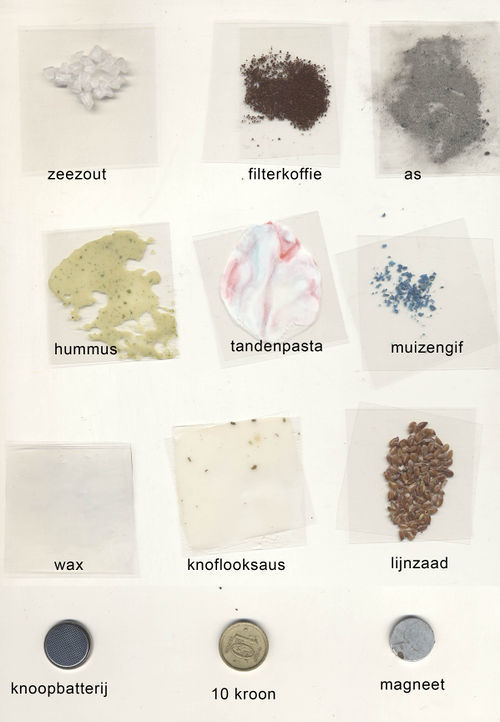
| + | [[File:Material-jw.jpg | 500px]] | ||
| + | |||
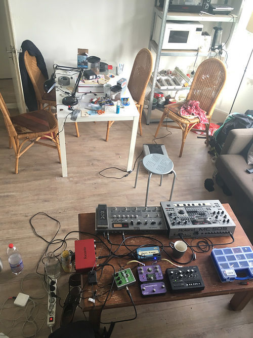
| + | [[File:Set-up.JPG | 500px]] | ||
==Project 3: Mind (of) the Machine== | ==Project 3: Mind (of) the Machine== | ||
Revision as of 12:02, 12 October 2017
work in progress
Contents
Project 1: On The Body
Teammate: Tim Reuser
Concept
Attempt 1
Attempt 2
Project 2: Inhuman Factors / Sensitivity Training
Teammate: Jochem Walboomers
Mouse scanner
Webcam microscope
Project 3: Mind (of) the Machine
Teammate: Alex Laman
The concept
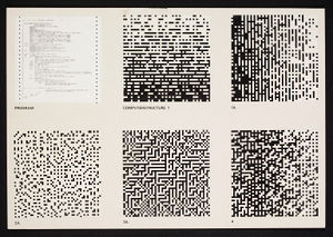
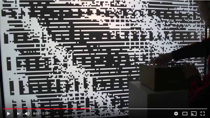
For this project we wanted to make a machine mind for which the user would make the connections between the different chambers of the brain. The visual output is based on Peter Struyckens Computer Structures.
The hardware
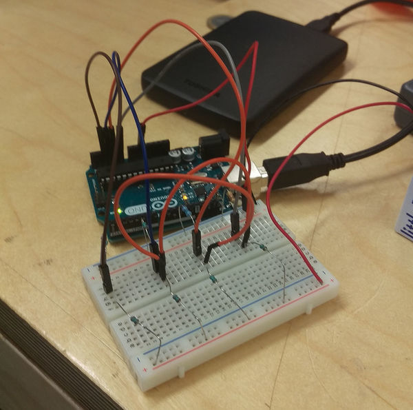
The idea was that by making voltage dividers for every input plug we would be able to identify which input plugs are connected on the arduino.
Below you see the first prototype on a breadboard with some voltage dividers, here we found that when you connect two of the circuits the resistance (or rather, the voltage) of these two would become the same. This is how we tell the arduino that two plugs are connected.
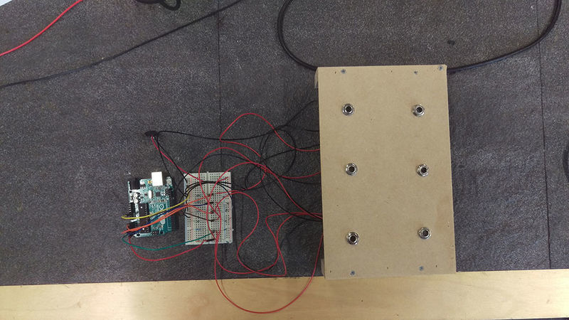
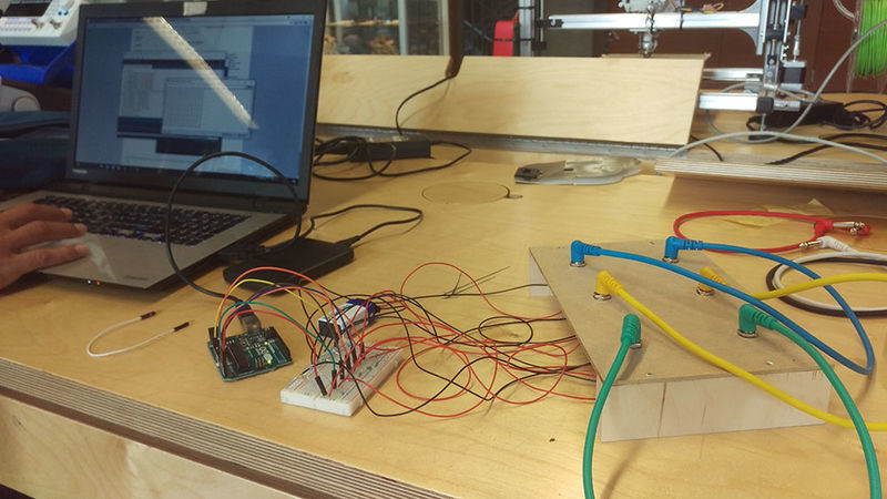
Then we made a panel with jack inputs and connected it to the breadboard to see if this would still hold up.
We can see on the computer that when no cables are connected we get six different numbers, as soon as we make a connection the numbers of the corresponding jack inputs become the same.
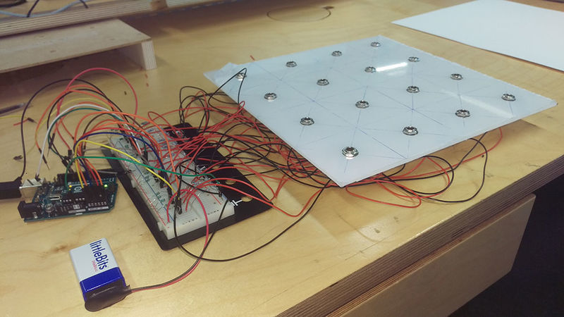
Then we made the top panel for the box from semi transparent perspex, we expanded to sixteen voltage dividers, using different resistors for every input.
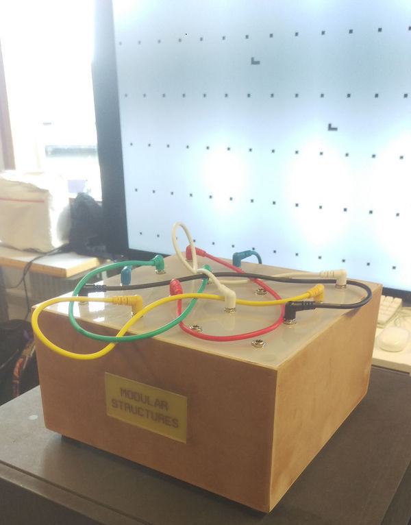
The finished box with title and short legs under it.
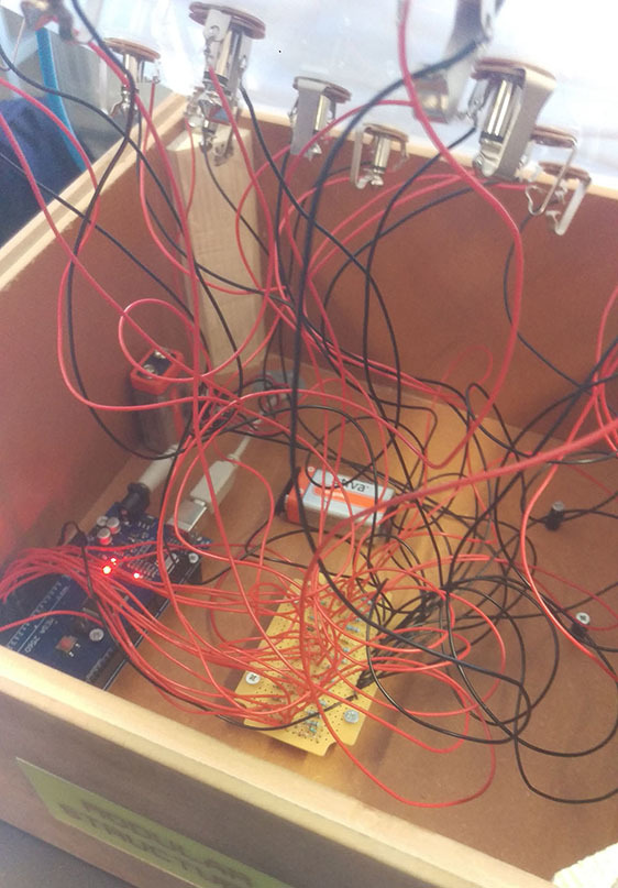
We made a system with magnets to seal the top panel to the box, we soldered the circuit and mounted everything in the box. You can shake the box or hold it upside down and it won't break. We wanted to make it as durable as possible.
The software
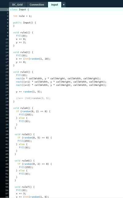
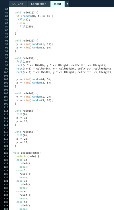
There are two programs at work, code on the arduino that sends the numerical values associated with the jack plugs to an external computer, and software made in processing that uses this data. The processing code is built up in "rules". Every jack input has its own set of rules on where to draw squares, by combining two jack inputs these rules will work together to make an image.
Here you see how the rules are structured
testing some connections on the computer
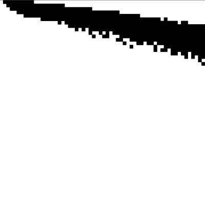
One connection
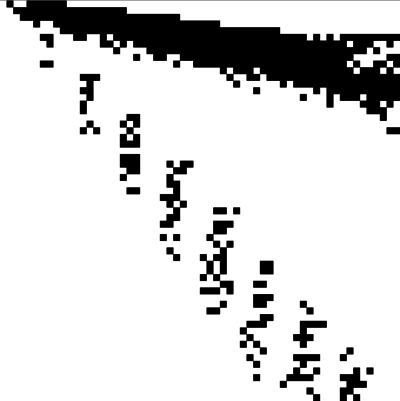
Two connections
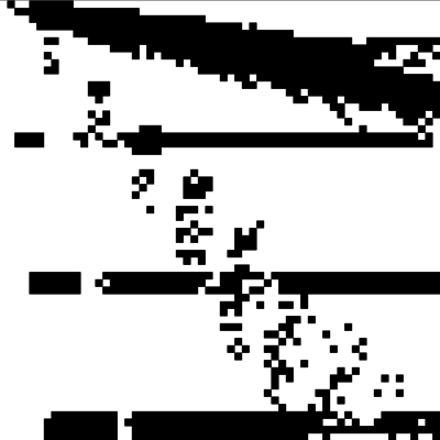
Three
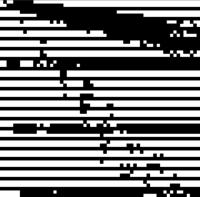
Four
Final result
>>>>>>>>>>>>> https://www.youtube.com/watch?v=0VKLEXFlaww <<<<<<<<<<<<<
