Difference between revisions of "User:O.Evans.A.Ram"
| Line 19: | Line 19: | ||
| + | '''SKETCHES//''' | ||
Below are photographs of our initial sketches, we searched for help from the interaction station and the material station and made sure we planned out our measurements so they are precise in order for our plans to become a realisation. | Below are photographs of our initial sketches, we searched for help from the interaction station and the material station and made sure we planned out our measurements so they are precise in order for our plans to become a realisation. | ||
| Line 29: | Line 30: | ||
[[File:Measurementsdesign.jpeg|200px]] | [[File:Measurementsdesign.jpeg|200px]] | ||
| + | |||
| + | |||
| + | '''PROTOTYPE//''' | ||
We then made a cardboard prototype of our design to check it would work mechanically. Below are photographs and a GIF of our design in use. | We then made a cardboard prototype of our design to check it would work mechanically. Below are photographs and a GIF of our design in use. | ||
| Line 43: | Line 47: | ||
[[File:Cardboardprototype2.gif|200px]] | [[File:Cardboardprototype2.gif|200px]] | ||
| + | |||
| + | '''TESTING OUR DESIGN//''' | ||
| Line 85: | Line 91: | ||
| + | '''ASSEMBLY//''' | ||
we then decided to design the other mechanisms on illustrator, and cut them out on one piece of wood measuring 600mm x 300mm and 3mm thick. | we then decided to design the other mechanisms on illustrator, and cut them out on one piece of wood measuring 600mm x 300mm and 3mm thick. | ||
Revision as of 13:34, 24 September 2018
DIGITAL CRAFT//THE SLEEP BOX//
We were set the task to ‘Design and make in 3D a new relationship between a living organism and a machine’.
RESEARCH//
We began by researching into cyborgs, and how machines can assist both nature and the human race in their daily lives. We were fascinated by this subject area and wanted to develop an machine that could improve our lives in a healthier way. Sleep is something that we are dependant on; we cannot function normally without it and sleep deprivation is a problem worldwide. A constant tick or white noise from a mechanism can assist people to drift asleep without the need for medication such as sleeping pills. Therefore, we decided to create a ‘sleep box’.
We were also inspired by rain, it is a relaxing noise, produced by nature, and we wanted to mimick that within our own machine. Our main priority is to create a machine that can be placed at the user´s bedside table and be able to help them soundly drift asleep.
An interesting Article from the BBC, delving into how nature and machine can become one.//
http://www.bbc.com/earth/story/20150703-can-nature-and-technology-be-friends[[1]]
Sourced from The BBC.
SKETCHES//
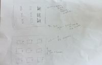
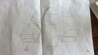
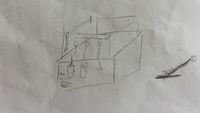
Below are photographs of our initial sketches, we searched for help from the interaction station and the material station and made sure we planned out our measurements so they are precise in order for our plans to become a realisation.
PROTOTYPE//
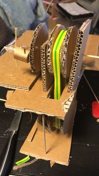
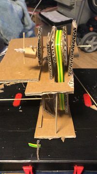
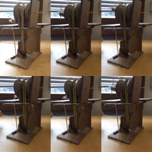
We then made a cardboard prototype of our design to check it would work mechanically. Below are photographs and a GIF of our design in use.
TESTING OUR DESIGN//
It was successful so then we planned to create the cogs and design from laser cut wood, at a thickness of 3mm. We planned to add a AC motor with 1.5v batteries. We are aware at this point that the motor would turn the system very quickly, too quickly unfortunately; we decided we can develop this later on in the process slowing the system down by using Arduino software.
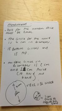
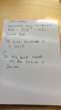
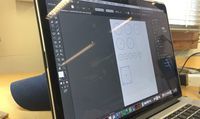
We used illustrator to draw out the cogs and parts to assemble the device in wood; below are photographs of the measurements and rules we set and abided by for all 9 working mechanisms we plan to make within the ‘sleep box’.
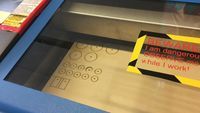
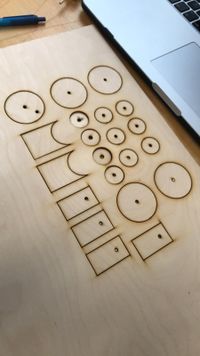
We then used the laser cutter to precisely cut out our parts. Below are photographs of the process.
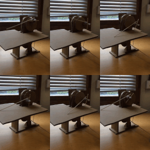
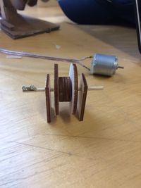
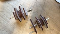
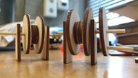
Once completed we assembled them roughly to check our measurements were correct. We now knew that we were correct, so we completed the first mechanism, and plan to finish the other eight. Shown below are photographs of the first completed mechanism, both top and bottom parts of the cog system.
ASSEMBLY//
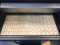
we then decided to design the other mechanisms on illustrator, and cut them out on one piece of wood measuring 600mm x 300mm and 3mm thick.
we will then assemble all cogs. in preperation to add the motors, and outer box and box underneath to house the AC motors.
