Difference between revisions of "From Device to Systems : Strobe Light"
Daankuyper (talk | contribs) |
Daankuyper (talk | contribs) |
||
| Line 8: | Line 8: | ||
<br> | <br> | ||
| − | [[file:IMG_5821.jpg|300px]] | + | [[file:IMG_5821.jpg|300px]] [[file:IMG_0921.jpg|300px]] |
<br> | <br> | ||
Revision as of 18:27, 31 October 2018
Starting Point
In my closet I had a Strobe light lying around which I bought just so I could use it one day. Luckely this project lended itself perfectly for this. I chose to take this strobe light apart and examine the elements combined to create this machine.
Open It Up
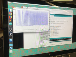
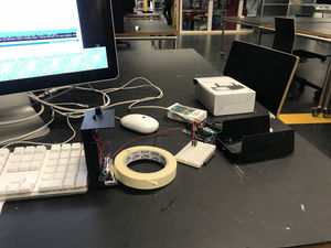
When I first opened it I saw a few different things. I found an on/off switch, a potentiometer, 2 bright LED ligts, a motherboard, a oscillator and a set of batteries. After testing it and seeing what everything does I found out that the way it works is that there is a on/off switch which turns on and cuts the power to the LED's. Next the current flows through the oscillator which creates oscillations (waves of current swinging up and down) These oscillations are being controlled by the potentiometer which says how much oscillation per second it should make. I tested this using a photocell attached to an Arduino board.
Prototyping
In this face I tested the Zoetrope effect. Where when a strobe light is introduced to a moving object and the movement of the object matches the oscillations of the light the movement looks like in slow motion. I tested this with a motor and a disk attached to the motor. This motor was powered by the Arduino board aswell.


