Difference between revisions of "T&T Confettinator"
B.Smulders (talk | contribs) |
|||
| (6 intermediate revisions by the same user not shown) | |||
| Line 1: | Line 1: | ||
==THE PROJECT== | ==THE PROJECT== | ||
| − | We knew that our enemy was going build a confetti machine so we had to build a | + | We knew that our 'enemy' was going build a confetti machine so we had to build a robot that counters it. We talked about different options like : magnetic field (van de graaf generator), static charge, flamethrower and stickiness. |
| + | ====research==== | ||
First we started doing research about the magnetic field but we realized that it wouldn't be possible because it couldn't be close to electric devices. | First we started doing research about the magnetic field but we realized that it wouldn't be possible because it couldn't be close to electric devices. | ||
Then we thought about applying sticky material to the wheels that would collect the confetti the most efficient way. We tried to put clothing rollers, different types of tapes to the wheels. We didn't choose to use this as the main function because we wanted to add a more technical approach. | Then we thought about applying sticky material to the wheels that would collect the confetti the most efficient way. We tried to put clothing rollers, different types of tapes to the wheels. We didn't choose to use this as the main function because we wanted to add a more technical approach. | ||
| − | We looked at options and choose to use a ventilator that could blow away the confetti. We wanted to operate the ventilator remotely controlled. | + | We looked at options and choose to use a ventilator that could blow away the confetti. We wanted to operate the ventilator remotely controlled. We opened the car to see how the electrical part is working. Our car is radio controlled. The transmitter sends a control signal to the receiver using radio waves, which then drives the motor. It has two motors, one in the back to control the speed and one in the front that controls the directions. |
| − | We opened the car to see how the electrical part is working. Our car is radio controlled. The transmitter sends a control signal to the receiver using radio waves, which then drives the motor. It has two motors, one in the back to control the speed and one in the front that controls the directions. | ||
| − | We realized that if we would only connect the ventilation to the speed of the car, it wouldn't be efficient because we had to drive fast for a optimum operation. To operate the ventilator from a distance like the car, we wanted to control it separately. We decided to hack a doorbell. We found out after researching all the components separately that the chips looks a lot like the chips of the radio controlled car. | + | We realized that if we would only connect the ventilation to the speed of the car, it wouldn't be efficient because we had to drive fast for a optimum operation. To operate the ventilator from a distance like the car, we wanted to control it separately. We decided to hack a doorbell. We found out after researching all the components separately that the chips looks a lot like the chips of the radio controlled car. The preset features like turning left and right, forward en backward where used for the different tunes. While trying to figure out what the pulse voltage was it wasn't working anymore. The reason was that when you touch the radio-tranciever the frequency changes slightly, what resulted in a de-sinc of the sender and receiver. |
We also attach an external battery to the arduino. The board can operate on an external supply of 6 to 20 volts. The recommended range is 7 to 12 volts. We used 9 V. We connected the + end of your battery to Arduino Vin and the - end to Arduino ground. The green light on the Arduino turned on to indicate that it is powered. | We also attach an external battery to the arduino. The board can operate on an external supply of 6 to 20 volts. The recommended range is 7 to 12 volts. We used 9 V. We connected the + end of your battery to Arduino Vin and the - end to Arduino ground. The green light on the Arduino turned on to indicate that it is powered. | ||
| − | Group roles | + | ====Group roles==== |
| + | We build the confetti machine together. Each person did research about an option we could use. The writing and wiki we did together. | ||
==CODE== | ==CODE== | ||
| Line 104: | Line 105: | ||
==PROCESS PICTURES== | ==PROCESS PICTURES== | ||
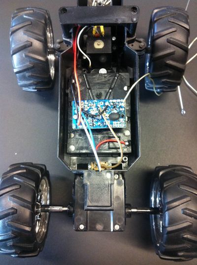
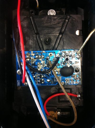
| − | [[File:IMG | + | [[File:IMG 7904.JPG|thumb|400px|The inside of the purchased RC car. The antenna was a loose wire; we had to strengen it wit and steel thread.|left]] |
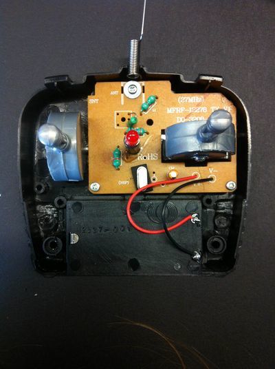
| − | + | [[File:IMG 7906.JPG|thumb|400px|left|The chip of the RX car. the chip name was covered with wax, it made the chip sheat unfindable.]] | |
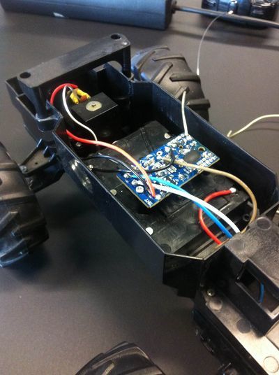
| − | + | [[File:IMG 7908.JPG|thumb|400px|left|The car has two motors: On the back a big one that made the car able to go back and fourth. And a smaller weaker one on the front for the turning.]] | |
| − | + | [[File:IMG 7910.JPG|thumb|400px|left|The inside was not glued and made rebuilding a bit difficult.]] | |
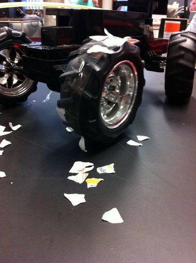
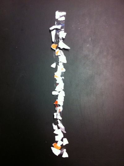
| − | + | [[File:Foto 06-10-14 10 47 35.jpg|thumb|400px|left|experiment with tape. We wanted to look if confetti would stick. And if the motor was strong enough so that it wouldn't be sticked to the surface.]] | |
| − | + | [[File:Foto 06-10-14 10 54 12.jpg|thumb|400px|left|Result od the sticking experiment.]] | |
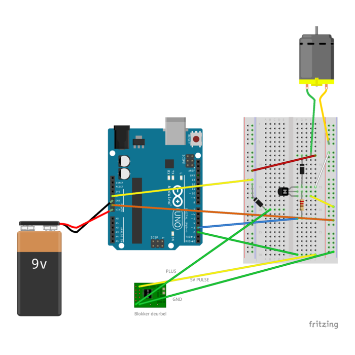
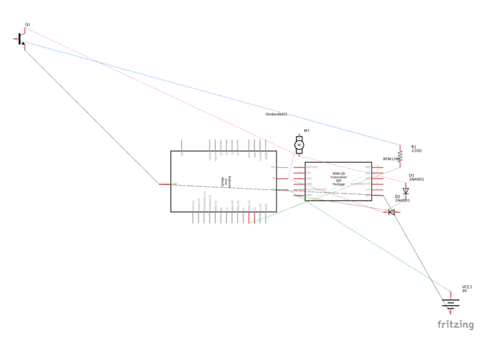
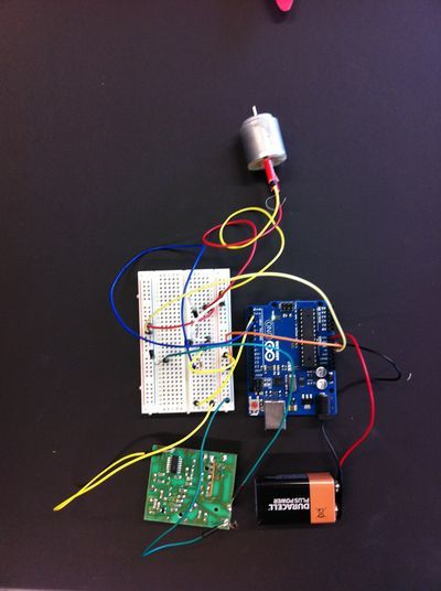
| − | [[File:IMG 7906.JPG|400px]] | + | [[File:Foto 27-10-14 11 20 48.jpg|thumb|400px|left|The entire circuit before it was attached to the RC car.]] |
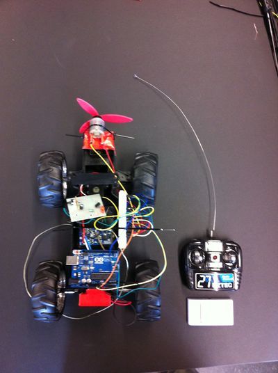
| − | + | [[File:Foto 27-10-14 11 51 31.jpg|thumb|400px|The entire setup.|left]] | |
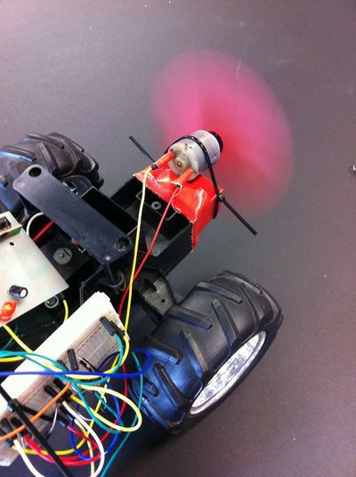
| − | [[File:IMG 7908.JPG|400px]] | + | [[File:Foto 27-10-14 11 54 32.jpg|thumb|400px|Fan working.|left]] |
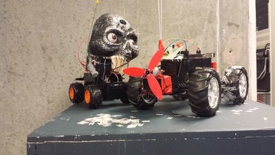
| − | + | [[File:20141028 103649.jpg|thumb|400px|Our robot next to his arch nemesis. from [http://opensource.wdka.nl/wiki/Group2 Group 2]|left]] | |
| − | [[File:IMG 7910.JPG|400px]] | ||
| − | |||
| − | [[File:Foto 06-10-14 10 47 35.jpg|400px]] | ||
| − | |||
| − | [[File:Foto 06-10-14 10 54 12.jpg|400px]] | ||
| − | |||
| − | [[File:Foto 27-10-14 11 20 48.jpg|400px]] | ||
| − | |||
| − | [[File:Foto 27-10-14 11 51 31.jpg|400px]] | ||
| − | |||
| − | [[File:Foto 27-10-14 11 54 32.jpg|400px]] | ||
Latest revision as of 16:51, 28 October 2014
THE PROJECT
We knew that our 'enemy' was going build a confetti machine so we had to build a robot that counters it. We talked about different options like : magnetic field (van de graaf generator), static charge, flamethrower and stickiness.
research
First we started doing research about the magnetic field but we realized that it wouldn't be possible because it couldn't be close to electric devices. Then we thought about applying sticky material to the wheels that would collect the confetti the most efficient way. We tried to put clothing rollers, different types of tapes to the wheels. We didn't choose to use this as the main function because we wanted to add a more technical approach.
We looked at options and choose to use a ventilator that could blow away the confetti. We wanted to operate the ventilator remotely controlled. We opened the car to see how the electrical part is working. Our car is radio controlled. The transmitter sends a control signal to the receiver using radio waves, which then drives the motor. It has two motors, one in the back to control the speed and one in the front that controls the directions.
We realized that if we would only connect the ventilation to the speed of the car, it wouldn't be efficient because we had to drive fast for a optimum operation. To operate the ventilator from a distance like the car, we wanted to control it separately. We decided to hack a doorbell. We found out after researching all the components separately that the chips looks a lot like the chips of the radio controlled car. The preset features like turning left and right, forward en backward where used for the different tunes. While trying to figure out what the pulse voltage was it wasn't working anymore. The reason was that when you touch the radio-tranciever the frequency changes slightly, what resulted in a de-sinc of the sender and receiver.
We also attach an external battery to the arduino. The board can operate on an external supply of 6 to 20 volts. The recommended range is 7 to 12 volts. We used 9 V. We connected the + end of your battery to Arduino Vin and the - end to Arduino ground. The green light on the Arduino turned on to indicate that it is powered.
Group roles
We build the confetti machine together. Each person did research about an option we could use. The writing and wiki we did together.
CODE
We took an existing code and modified it for our purpose.
original code:
/*
Adafruit Arduino - Lesson 13. DC Motor
*/


int motorPin = 3;

void setup()
{
  pinMode(motorPin, OUTPUT);
  Serial.begin(9600);
  while (! Serial);
  Serial.println("Speed 0 to 255");
}


void loop()
{
  if (Serial.available())
  {
    int speed = Serial.parseInt();
    if (speed >= 0 && speed <= 255)
    {
      analogWrite(motorPin, speed);
    }
  }
}
Midified code: Changes in the code
/*
Adafruit Arduino - Lesson 13. DC Motor
*/


int motorPin = 3;
int buttonPin = 2;
int led=13;
int speed = 255;

void setup()
{
  pinMode(motorPin, OUTPUT);
  pinMode(buttonPin, INPUT);
  pinMode(led, OUTPUT);
  digitalWrite(motorPin, LOW);

  //analogWrite(motorPin, speed);
}


void loop()
{
if (digitalRead(buttonPin));
  // read the state of the pushbutton value:
  int buttonState = digitalRead(buttonPin);

  // check if the pushbutton is pressed.
  // if it is, the buttonState is HIGH:
  if (buttonState == HIGH) {
    // turn LED on:
    digitalWrite(led, HIGH);
    digitalWrite(motorPin, HIGH);
  }

  else {
    // turn LED off:
    digitalWrite(led, LOW);
    digitalWrite(motorPin, LOW);
  }
}
CIRCUIT
PROCESS PICTURES
