Difference between revisions of "User:Mantaskosmo"
Mantaskosmo (talk | contribs) |
Mantaskosmo (talk | contribs) |
||
| (12 intermediate revisions by the same user not shown) | |||
| Line 4: | Line 4: | ||
'''"Rhythmical staircase"''' is a project created in order to increase visitors spatial averseness. “Rhythmical Staircase” installation translate the rhythmical movement of walking through the stairs into proverbially equivalent “one, two, one, …”. | '''"Rhythmical staircase"''' is a project created in order to increase visitors spatial averseness. “Rhythmical Staircase” installation translate the rhythmical movement of walking through the stairs into proverbially equivalent “one, two, one, …”. | ||
| + | |||
| + | https://www.youtube.com/watch?v=8M_w4xgZjI8 | ||
| Line 15: | Line 17: | ||
Roughly, the installation is made of two circuits - one is a IR (infrared) LED light circuit, and photodiodes circuit. LED circuit is connected to 9V power source and photodiodes circuit is connected to Arduino MEGA which is later programmed in processing. Photodiodes are installed on a side of a staircase and directed to a LED light in the other side of a stair. Once the light is covered, photodiode value drops to minimum and that triggers processing to play the sound. | Roughly, the installation is made of two circuits - one is a IR (infrared) LED light circuit, and photodiodes circuit. LED circuit is connected to 9V power source and photodiodes circuit is connected to Arduino MEGA which is later programmed in processing. Photodiodes are installed on a side of a staircase and directed to a LED light in the other side of a stair. Once the light is covered, photodiode value drops to minimum and that triggers processing to play the sound. | ||
| + | |||
| + | [[File:Model-02.jpg]] | ||
| Line 20: | Line 24: | ||
'''13 IR LED lights''' ( I used Kingbright T-1 3/4 (5mm)) | '''13 IR LED lights''' ( I used Kingbright T-1 3/4 (5mm)) | ||
| + | |||
'''13 Photodiodes''' ( I used Taos TSL260R ) | '''13 Photodiodes''' ( I used Taos TSL260R ) | ||
| + | |||
'''Arduino MEGA''' ( if you use up to 6 staircase you can also use Arduino UNO which has 6 analog inputs instead of 13. (It is possible to use Arduino UNO for more than 6 staircase but the instructions than different )). | '''Arduino MEGA''' ( if you use up to 6 staircase you can also use Arduino UNO which has 6 analog inputs instead of 13. (It is possible to use Arduino UNO for more than 6 staircase but the instructions than different )). | ||
| + | |||
'''Wires''' ( depending on your circuits, the size of the staircase, also how far is the ‘station' (computer and power source)) I used around 200 meters of wires and my ‘station’ was about 2 meter from the circuits. | '''Wires''' ( depending on your circuits, the size of the staircase, also how far is the ‘station' (computer and power source)) I used around 200 meters of wires and my ‘station’ was about 2 meter from the circuits. | ||
| + | |||
'''9V power adapter''' ( for LED circuit) | '''9V power adapter''' ( for LED circuit) | ||
| + | |||
'''2x 1ohms resistor''' ( for LED circuit) | '''2x 1ohms resistor''' ( for LED circuit) | ||
| + | |||
'''390ohms resistor''' ( for LED circuit) | '''390ohms resistor''' ( for LED circuit) | ||
| + | |||
'''Arduino app''' | '''Arduino app''' | ||
| + | |||
'''Processing app''' | '''Processing app''' | ||
| + | |||
| Line 34: | Line 47: | ||
For my circuit I used this array. If you will use different LED or power supply, you can calculate your array here: http://led.linear1.org/led.wiz | For my circuit I used this array. If you will use different LED or power supply, you can calculate your array here: http://led.linear1.org/led.wiz | ||
| − | [[ | + | [[File:Screen Shot 2015-06-28 at 19.04.02.png]] |
| + | |||
'''Photodiodes Circuit''' | '''Photodiodes Circuit''' | ||
| + | |||
Photodiode have 3 pins. Ground (GND) and Power supply pin (VDD) circuits should be connected to Arduino GND and 5V inputs. 3rd pin is an output which separately have to be connected to Arduino analog input. | Photodiode have 3 pins. Ground (GND) and Power supply pin (VDD) circuits should be connected to Arduino GND and 5V inputs. 3rd pin is an output which separately have to be connected to Arduino analog input. | ||
| + | |||
| + | [[File:Screen Shot 2015-06-28 at 20.34.49.png]] | ||
Photodiodes connected in GND and VDD circuit. | Photodiodes connected in GND and VDD circuit. | ||
| + | |||
| + | [[File:IMG 2010.JPG]] | ||
| + | |||
I am highly recommending to use different colours wires for GND and VDD circuits. | I am highly recommending to use different colours wires for GND and VDD circuits. | ||
| + | |||
| + | [[File:IMG 2011.JPG]] | ||
The whole circuit will look like this at the end. | The whole circuit will look like this at the end. | ||
| + | |||
| + | [[File:IMG 2013.JPG]] | ||
Photodiodes connected to Arduino. Big amount of wires requires good infrastructure that’s why I recommend to number wires or use different colours wires. | Photodiodes connected to Arduino. Big amount of wires requires good infrastructure that’s why I recommend to number wires or use different colours wires. | ||
| + | |||
| + | [[File:IMG 2012.JPG]] | ||
Photodiodes are sensitive from all the sides. To make it directed to LED light source you have to make ‘a tunnel’ which would isolate sensor from surrounded light and would be directed only to a LED lights in the other side of a stair. | Photodiodes are sensitive from all the sides. To make it directed to LED light source you have to make ‘a tunnel’ which would isolate sensor from surrounded light and would be directed only to a LED lights in the other side of a stair. | ||
| + | [[File:IMG 2026.JPG]] [[File:IMG 2025.JPG]] | ||
| + | |||
| + | Photodiodes sticked to the side of the staircase before hiding wires under the tape. | ||
| + | |||
| + | |||
| + | '''Arduino app''' | ||
| − | |||
First of all you will probably want to check photodiodes incoming value. | First of all you will probably want to check photodiodes incoming value. | ||
To check it you can use this code: | To check it you can use this code: | ||
| + | |||
| + | [[File:AnalogReadSerial.txt]] | ||
| Line 63: | Line 96: | ||
To connect, use this code: | To connect, use this code: | ||
| + | [[File:SendingValue.txt]] | ||
| + | |||
| + | |||
| + | '''Processing app''' | ||
| − | |||
Processing code connected with audio files and Arduino app: | Processing code connected with audio files and Arduino app: | ||
| + | |||
| + | [[File:ProcessCode.txt]] | ||
Processing code is linked with audio files which had to be uploaded on the same directory as code file. | Processing code is linked with audio files which had to be uploaded on the same directory as code file. | ||
| + | |||
| + | |||
| + | |||
| + | |||
| + | |||
| + | '''Special thanks:''' | ||
| + | |||
| + | Simon de Baker | ||
| + | |||
| + | Thomas Rutgers | ||
| + | |||
| + | Brigit Lichtenegger | ||
| + | |||
| + | Gabrielle Marks | ||
| + | |||
| + | Anja Groten | ||
| + | |||
| + | |||
| + | Mantas Rimkus “Rhythmical Staircase” | ||
| + | 2015 | ||
Latest revision as of 09:07, 1 July 2015
Rhythmical Staircase
"Rhythmical staircase" is a project created in order to increase visitors spatial averseness. “Rhythmical Staircase” installation translate the rhythmical movement of walking through the stairs into proverbially equivalent “one, two, one, …”.
https://www.youtube.com/watch?v=8M_w4xgZjI8
Concept
The meeting between body and world is natural as well as culturally and conventionally produced. The rhythmic experience is likely to be found in aesthetic of visual and audible movement. Rhythm is multisensory and appeals to our tactile, visual, and sonic senses. The stair is an architectural part that appeals to all the senses. The stair meets us as a passage and a sequence experienced over time. It’s ‘here and now’ experience which coordinates with memories of past experience and what is present. The movement in a staircase leads up and down, and physically it is the part of the building that interacts with our bodies. Visually, the movement is already inscribed as a repetition in construction, which audibly can be described as the rhythm of the steps echoing, the beating of the heart and the rhythm of breathing. It is natural for us so we don’t think about it. In order to increase visitors spatial averseness “Rhythmical Staircase” installation translate the rhythmical movement of walking through the stairs into proverbially equivalent “one, two, one, ...”
Progress
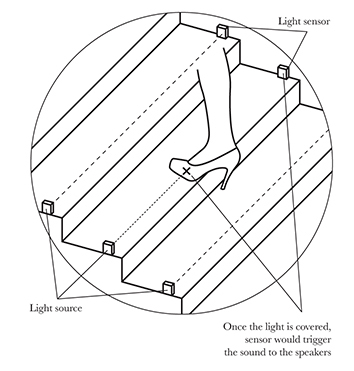
Roughly, the installation is made of two circuits - one is a IR (infrared) LED light circuit, and photodiodes circuit. LED circuit is connected to 9V power source and photodiodes circuit is connected to Arduino MEGA which is later programmed in processing. Photodiodes are installed on a side of a staircase and directed to a LED light in the other side of a stair. Once the light is covered, photodiode value drops to minimum and that triggers processing to play the sound.
To make 13 interactive stairs you will need:
13 IR LED lights ( I used Kingbright T-1 3/4 (5mm))
13 Photodiodes ( I used Taos TSL260R )
Arduino MEGA ( if you use up to 6 staircase you can also use Arduino UNO which has 6 analog inputs instead of 13. (It is possible to use Arduino UNO for more than 6 staircase but the instructions than different )).
Wires ( depending on your circuits, the size of the staircase, also how far is the ‘station' (computer and power source)) I used around 200 meters of wires and my ‘station’ was about 2 meter from the circuits.
9V power adapter ( for LED circuit)
2x 1ohms resistor ( for LED circuit)
390ohms resistor ( for LED circuit)
Arduino app
Processing app
IR LED lights circuit
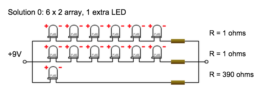
For my circuit I used this array. If you will use different LED or power supply, you can calculate your array here: http://led.linear1.org/led.wiz
Photodiodes Circuit
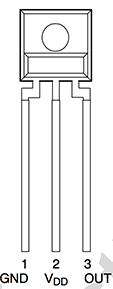
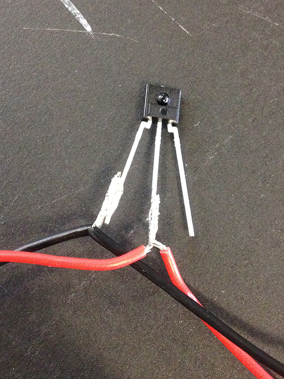
Photodiode have 3 pins. Ground (GND) and Power supply pin (VDD) circuits should be connected to Arduino GND and 5V inputs. 3rd pin is an output which separately have to be connected to Arduino analog input.
Photodiodes connected in GND and VDD circuit.
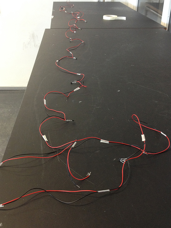
I am highly recommending to use different colours wires for GND and VDD circuits.
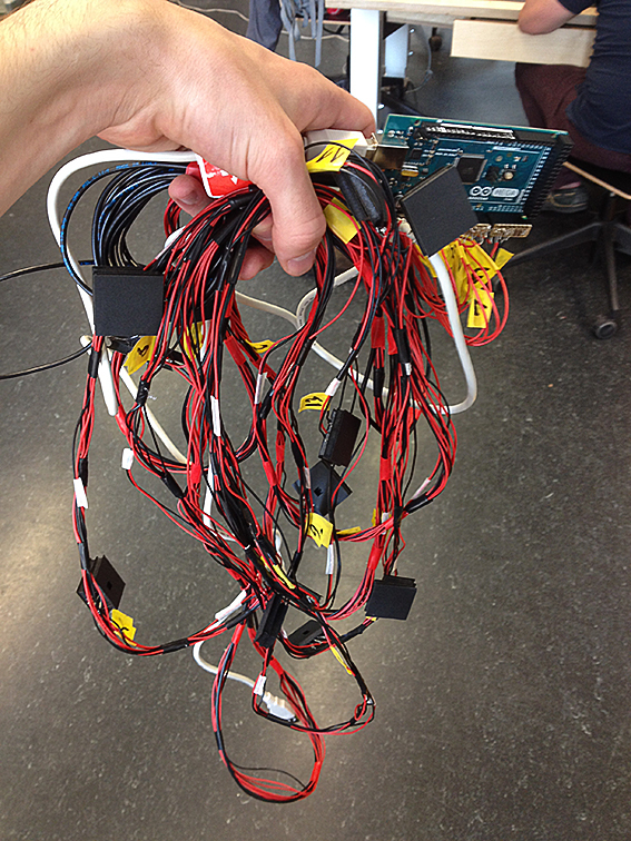
The whole circuit will look like this at the end.
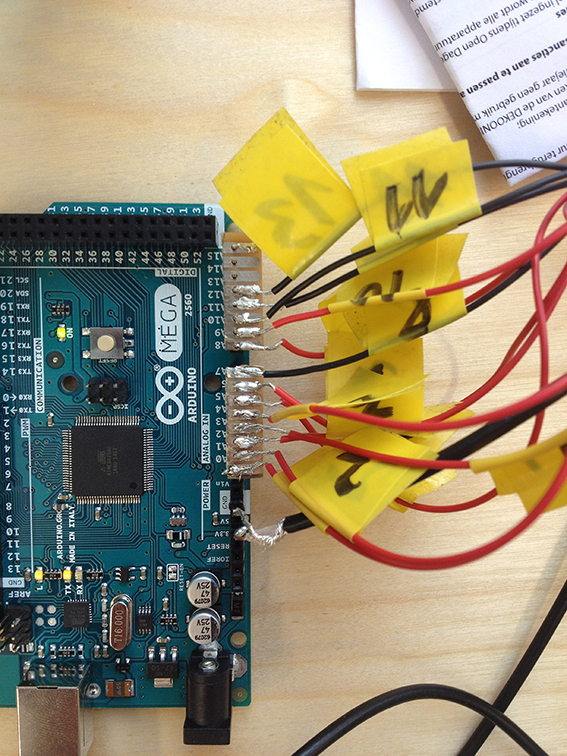
Photodiodes connected to Arduino. Big amount of wires requires good infrastructure that’s why I recommend to number wires or use different colours wires.
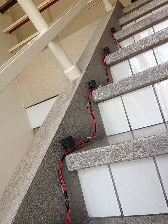
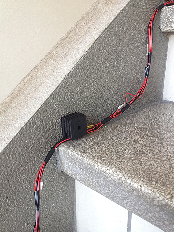
Photodiodes are sensitive from all the sides. To make it directed to LED light source you have to make ‘a tunnel’ which would isolate sensor from surrounded light and would be directed only to a LED lights in the other side of a stair.
Photodiodes sticked to the side of the staircase before hiding wires under the tape.
Arduino app
First of all you will probably want to check photodiodes incoming value. To check it you can use this code:
The value from photodiodes should be sent to Processing app.
To connect, use this code:
Processing app
Processing code connected with audio files and Arduino app:
Processing code is linked with audio files which had to be uploaded on the same directory as code file.
Special thanks:
Simon de Baker
Thomas Rutgers
Brigit Lichtenegger
Gabrielle Marks
Anja Groten
Mantas Rimkus “Rhythmical Staircase”
2015
