Difference between revisions of "User:Oliscotton"
Oliscotton (talk | contribs) |
Oliscotton (talk | contribs) |
||
| (170 intermediate revisions by the same user not shown) | |||
| Line 1: | Line 1: | ||
| + | =Hello= | ||
| + | |||
| + | I'm '''Oli Scotton'''. A graphic design student on exchange from Bristol, UK. [[File:Olipic.jpg | thumb]] | ||
| + | |||
| + | |||
| + | Email: '''0923547@hr.nl''' | ||
| + | |||
| + | |||
| + | |||
| + | |||
=Digital Craft= | =Digital Craft= | ||
| − | 1. | + | ==Intro== |
| + | |||
| + | 1. The moment I knew what I wanted to do: | ||
| + | I once attended a talk from Sandy Suffield, who was previously a Senior Art Director at Apple, and a Creative Director at Wolff Olins. She explained that she wasn't happy in these roles, and decided to quit her job, and wanted to start making work that she wanted to make, to hopefully in return get freelance work based on her ideas. After this talk, I decided that it's always important to make projects for myself alongside my study/job. | ||
| + | |||
| + | 2. What do you make? | ||
| + | I like to make typography based work. Also enjoy experimenting with printing techniques. I'm also interested in photography, and would like to start incorporating this into my design work. | ||
| + | |||
| + | 3. What is your topic of interest? | ||
| + | I would like to start creating work on a larger scale as I often make printed work. I'd like to create a visually/physically engaging installation. | ||
| + | |||
| + | 4. What is your medium? | ||
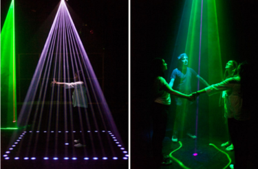
| + | I'd like to get more familiar with 3D printing, and try to incorporate this into a large installation. I'd also like to work with lasers and light beams. | ||
| + | |||
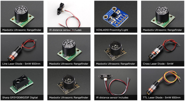
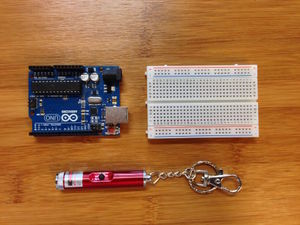
| + | [[File:Image1oli.png | 225px | 1]] [[File:Image2oli.jpg | 225px]] [[File:Image6oli.png | 300px]] [[File:Image4oli.jpg | 300px]] | ||
| + | |||
| + | |||
| + | ==Circuit Board== | ||
| + | |||
| + | In a group of 3 we created a simple circuit board that made a sound through a speaker when you press down on the touch sensor. It was my first time soldering something, so I needed someone else to hold the components with tweezers as I soldered it, as it was so small. It was a good introduction into circuit boards, although very fiddly. | ||
| + | '''Video of circuit board -->''' [https://www.youtube.com/watch?v=2d2FIpRylFA] | ||
| + | |||
| + | [[File:circuit1.JPG | 250px]] [[File:IMG 0388.JPG | 250px]] | ||
| + | |||
| + | ==Project== | ||
| + | |||
| + | |||
| + | I wrote down 20 words of things I could potentially focus on for my personal project. The 3 that I chose from the 20 were 'Interactive Installation', 'Sound' & 'Playful'. Because I normally create things for print or on a screen, I've always wanted to work on a large scale, or an installation. I want to create something visual, but also interactive. Initially I thought about using a plant as an instrument, that would make a noise when you touch it (using speakers), and to have a few different plants with different sounds. But I wanted to make something a little more visually appealing. I did like the idea of using a projector and mirrors to create interesting visuals, but then it didn't require any making (circuit boards). Another idea i've had for a while was someone wearing a suit of mirrors, rotating on a platform, then shine a laser at them, resulting in it reflecting of in various ways. Again, this is just a visual outcome. I then thought about combining the two sides, and thought about using lasers/light to create sound. I then had the idea of using 5/6 lasers that each have a different drum sound assigned to them. And would make a sound if you intersect the beam. It would then be both a visual and interactive piece. | ||
| + | |||
| + | [[File:List.jpg | 250px]] [[File:Sheet1.jpg | 250px]] [[File:Sheet4.jpg | 400px]] [[File:Sheet3.jpg | 250px]] [[File:Sheet2.jpg | 375px]] [[File:Laserdrawing2.JPG | 375px]] [[File:Ideasketch.jpg | 375px]] | ||
| + | |||
| + | [[File:similarwork.png | 375px]] [[File:Lasers1.png | 375px]] [[File:Lasers2.png | 375px]] | ||
| + | |||
| + | [[File:Laser3.jpg | 450px]] [[File:Laser4.png | 600px]] | ||
| + | |||
| + | I want to explore the idea of creating an electronic instrument using circuit boards and Arduino. I've never worked with circuit boards or Arduino before, so I decided this would be a good opportunity to learn something knew. I decided that I would use 1 laser pointer initially to see if I could get it to work, then if so, I would hopefully add more. I would position the laser to point at the LDR, and then once the light is intercepted, the light reading would drop, therefor triggering a sound from my laptop. | ||
| + | |||
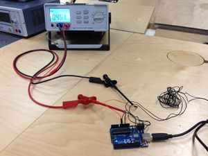
| + | I began looking online for similar projects to get an idea of what components I would need. I came across something called a 'laser harp' which seems to a pretty popular thing. It looks just like my original sketches. It seems a rather challenging thing to make, so I began looking for more basic DIY versions. I came across this project [http://makezine.com/projects/laser-harp/], but it seemed a bit too complex. I then started looking at laser trip wire projects as that's the very essence of what I wanted to achieve. I then came across this project [http://www.instructables.com/id/Arduino-Laser-Tripwire/] which seemed like a straightforward simple approach to what I wanted to achieve. I bought all of the components and started building my circuit using a breadboard. The pictures and instructions weren’t very clear, so it took me a little while to understand how to construct it. I decided to use the Arduino power output to power the laser pointer, although this makes the circuit messier. | ||
| + | |||
| + | [[File:arduinolaser.JPG | 300px]] [[File:digicraft1.JPG | 300px]] [[File:digicraft3.1.JPG | 300px]] [[File:digicraft3.JPG | 300px]] | ||
| − | + | [[File:digicraft4.JPG | 300px]] [[File:digicraft5.JPG | 300px]] [[File:digicraft6.JPG | 300px]] [[File:digicraft7.jpg | 300px]] | |
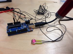
| − | 3. | + | Once I had 1 laser & LDR set up and working with Arduino, I decided to add another laser. Which became problematic in Arduino initially. I also decided to add 2 LEDs to make it easier for myself to check if everything was working as it should. I used 10 Ohm resistors for the for the LDR’s, and 3 Ohm resistors for the LEDs. It took a lot of moving things around and reconfiguring wires to get it them both working. To then transfer my circuit from a breadboard to a perf board, I drew out a simple schematic drawing. I used rows of pin to connect the circuit board directly to the Arduino. The first couple of wires I soldered were quite long, and this made them weaker because they started to bend. I decided to take them off and start again with my much smaller wires. I also didn’t solder the tips of the wires the first time, but when I did it made it so much easier. The lasers were connected to the board using crocodile clips, attached to wires that were soldered on. The problem with this is that the clips often came loose as they didn’t have much to attach too. But also the wires became weak and flimsy because they’re always bending. (RED CIRCLES INDICATE IN PHOTOS) I decided to wire the lasers directly to the board to make the connection stronger, but also less long wires made it easier to see what was going on. The last image shows an error that I received while trying to configure both LDRs. Looking online and trial & error solved the problem. |
| − | + | [[File:digicraft8.JPG | 300px]] [[File:digicraft9.JPG | 300px]] [[File:Olidigi8.JPG | 300px]] [[File:digicraft11.png | 300px]] | |
| + | |||
| + | [[File:digicraft12.png | 300px]] [[File:Variousmethods.png | 500px]] | ||
| + | |||
| + | The first images shows the Arduino code used (taken from ‘Arduino Laser Tripwire’ tutorial referenced earlier.) I needed to use Processing along side Arduino to make sounds played when the laser is intercepted. I’d never used Processing before so it was something knew again, but there seemed to be a lot of information online about it. I spent a lot of time trying various code to get my Arduino to interactive with Processing. Pictures show examples. This is the code I first tried. — > [http://cmuems.com/2013/b/sounds-with-arduino-and-processing/] | ||
| + | The problem seemed to be, connecting Arduino with Processing. I kept getting error in my Arduino code, such as "error: arduino was not declared in this scope”. I read on a forum that sometimes minim doesn’t work well on the latest version of Processing. So I downloaded version 1.5 but it wouldn’t run on my mac. Instead of minim, a lot of people suggested Firmata. It’s already installed into Arduino’s examples, so you can just open it inside the program. The difference is, with Firmata you upload all of the code onto the Arduino board, but then use processing to do the programming. I also ran into various problems with this. I read through countless forums to find an answer button couldn’t work it out. Some of the resources used —> [https://forum.processing.org/two/discussion/6041/need-help-to-play-a-file-whenever-a-button-is-pressed-via-the-arduino] [http://forum.arduino.cc/index.php?topic=19584.0] [http://stackoverflow.com/questions/35595457/using-serial-information-from-arduino-to-play-audio-in-processing] | ||
| + | |||
| + | |||
| + | [[File:Olidigi7.JPG | 300px]] [[File:digicraft14.JPG | 300px]] | ||
| + | |||
| + | I decided to make some kind of housing for the board and something to hide the wires. I laser cut a piece thing board, and then found a plastic casing from the back of a speaker that I would use to cover everything. I would then run the wires of the LDR underneath the board, onto the other side. I ran out of time mounting everything as I wanted because I spent so much time trying to get the sounds to play from computer. | ||
| + | |||
| + | What I'd do if I had more time: | ||
| + | |||
| + | If I had more time work on my project, I would make sure I could get sound to play for a start. I planned to assign a different 808 drum sample to each laser-trip, this could also then be changed to chords from different instruments. The piece that I presented didn't utilise the ability to work on a further distance. It would require me using batteries in the lasers so that they could be place far away from the LDRs. I could have then made the sounds happen once someone walks past, making it more interactive. I'd also add maybe another lasers, so that users could use different body parts to make the sounds as they'd be spread further apart. I'd also like to play with the idea of doing this in a pitch black room, so the user can only see the dots from the laser, but then come to realise that if they block them, it'll make sounds. Overall i'm satisfied with my outcome although I wish I could have finished it. I've learn how to use Arduino and how to make a circuit board, so I'm really happy with my progress in this project. | ||
| + | |||
| + | |||
| + | |||
| + | '''VIDEO TESTS & EXPERIMENTATION! --> [https://www.youtube.com/watch?v=3rzYtMv3OEU&feature=youtu.be] [https://www.youtube.com/watch?v=L57uP29iRbo] | ||
| + | ''' | ||
=Mimicking Machines= | =Mimicking Machines= | ||
| − | == | + | |
| + | ==Assignment 1== | ||
| + | '''I Draw. You Draw. It Draws''' | ||
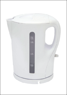
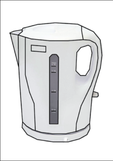
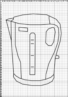
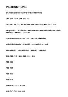
| + | I decided to choose a kettle for my machine. I found an image online, then traced it using the Pen Tool on Adobe Illustrator. Once I had the vector outline, I placed a grid on top of the drawing, and then plotted indices across each side. Rather than using x & y with numbers, I decided to use letters across the top, and numbers down the side. Because the grid was wider than 26 points, I decided to use upper and lowercase letters. Although I thought it was clear enough to understand, it did cause some confusion to the user when presented with the instructions. I also decided to tell the user to 'DRAW LINE FROM CENTRE OF EACH SQUARE' because I thought it would have been too complex otherwise. | ||
| + | The person trying to re-draw my machine got confused initially with the upper and lowercase letters, but once they had worked that out, they drew my machine just as I wanted. | ||
| + | |||
| + | [[File:Draw1.png | 220px]] [[File:Draw2.png | 220px]] [[File:Draw3.png | 220px]] [[File:Draw4.jpg | 220px]] [[File:Drawn1.jpg | 220px]] | ||
| + | |||
| + | ==Assignment 2== | ||
| + | '''The Extruded Milled and Sliced Alphabet''' | ||
| + | |||
| + | [[File:I.png | 220px]] [[File:I2.png | 220px]] [[File:MyI4.jpg | 220px]] [[File:OliMim1.JPG | 220px]] [[File:OliMim2.JPG | 220px]] | ||
| + | |||
| + | The 'I' I made was made from flat circular discs staked on top of each other, then a sphere on top attach by a small support in the centre. The shape I made was too large, so we scaled it down to 5cm in height. After this we had to decide wether it needed a support when printing, which it did. So we placed the shape vertically, because this way it needed less support material, which in return takes less time. It took a few goes to make sure the printer was calibrated correctly, and that it had enough space between the base and the extruder to print correctly. Because it's a small intricate model, it's hard to know what is the support material, and what isn't. Although it isn't exactly how I design it, I like the way the bottom half looks with the rough, pointy edges. | ||
| + | |||
| + | [[File:mimstl.JPG | 220px]] [[File:3dgif2loop.gif | 220px]] [[File:3dgifloop.gif | 220px]] [[File:3dgif3loop.gif | 220px]] [[File:finalletter.JPG | 220px]] | ||
| + | |||
| + | ==Assignment 3== | ||
| + | ""Human Powered Machine"" | ||
Latest revision as of 19:47, 24 June 2016
Contents
Hello
I'm Oli Scotton. A graphic design student on exchange from Bristol, UK.
Email: 0923547@hr.nl
Digital Craft
Intro
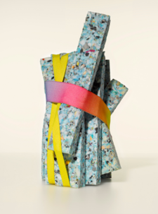
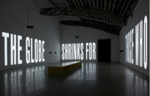
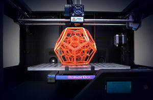
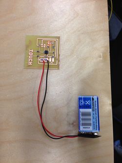
1. The moment I knew what I wanted to do: I once attended a talk from Sandy Suffield, who was previously a Senior Art Director at Apple, and a Creative Director at Wolff Olins. She explained that she wasn't happy in these roles, and decided to quit her job, and wanted to start making work that she wanted to make, to hopefully in return get freelance work based on her ideas. After this talk, I decided that it's always important to make projects for myself alongside my study/job.
2. What do you make? I like to make typography based work. Also enjoy experimenting with printing techniques. I'm also interested in photography, and would like to start incorporating this into my design work.
3. What is your topic of interest? I would like to start creating work on a larger scale as I often make printed work. I'd like to create a visually/physically engaging installation.
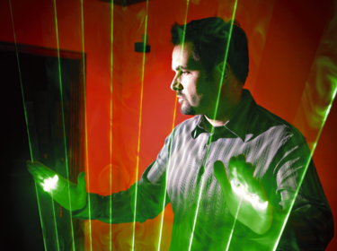
4. What is your medium? I'd like to get more familiar with 3D printing, and try to incorporate this into a large installation. I'd also like to work with lasers and light beams.
Circuit Board
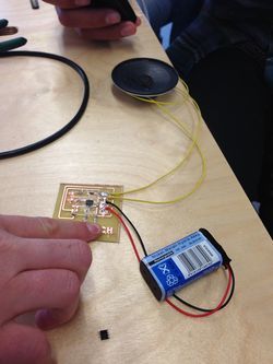
In a group of 3 we created a simple circuit board that made a sound through a speaker when you press down on the touch sensor. It was my first time soldering something, so I needed someone else to hold the components with tweezers as I soldered it, as it was so small. It was a good introduction into circuit boards, although very fiddly. Video of circuit board --> [1]
Project
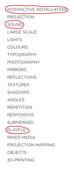
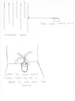
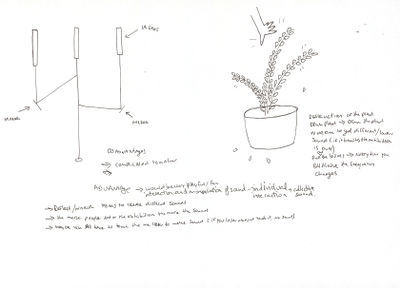
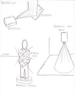
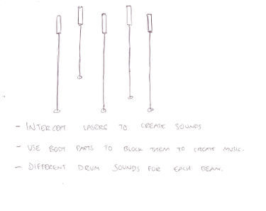
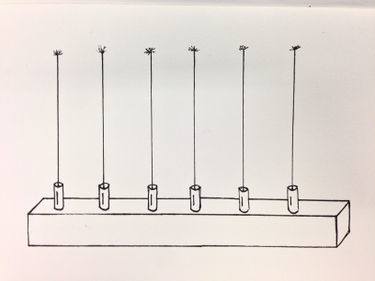
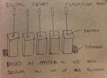
I wrote down 20 words of things I could potentially focus on for my personal project. The 3 that I chose from the 20 were 'Interactive Installation', 'Sound' & 'Playful'. Because I normally create things for print or on a screen, I've always wanted to work on a large scale, or an installation. I want to create something visual, but also interactive. Initially I thought about using a plant as an instrument, that would make a noise when you touch it (using speakers), and to have a few different plants with different sounds. But I wanted to make something a little more visually appealing. I did like the idea of using a projector and mirrors to create interesting visuals, but then it didn't require any making (circuit boards). Another idea i've had for a while was someone wearing a suit of mirrors, rotating on a platform, then shine a laser at them, resulting in it reflecting of in various ways. Again, this is just a visual outcome. I then thought about combining the two sides, and thought about using lasers/light to create sound. I then had the idea of using 5/6 lasers that each have a different drum sound assigned to them. And would make a sound if you intersect the beam. It would then be both a visual and interactive piece.
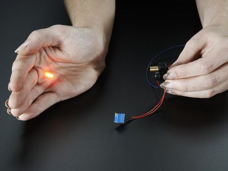
I want to explore the idea of creating an electronic instrument using circuit boards and Arduino. I've never worked with circuit boards or Arduino before, so I decided this would be a good opportunity to learn something knew. I decided that I would use 1 laser pointer initially to see if I could get it to work, then if so, I would hopefully add more. I would position the laser to point at the LDR, and then once the light is intercepted, the light reading would drop, therefor triggering a sound from my laptop.
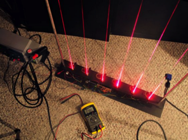
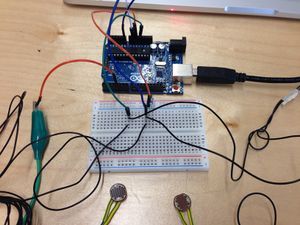
I began looking online for similar projects to get an idea of what components I would need. I came across something called a 'laser harp' which seems to a pretty popular thing. It looks just like my original sketches. It seems a rather challenging thing to make, so I began looking for more basic DIY versions. I came across this project [2], but it seemed a bit too complex. I then started looking at laser trip wire projects as that's the very essence of what I wanted to achieve. I then came across this project [3] which seemed like a straightforward simple approach to what I wanted to achieve. I bought all of the components and started building my circuit using a breadboard. The pictures and instructions weren’t very clear, so it took me a little while to understand how to construct it. I decided to use the Arduino power output to power the laser pointer, although this makes the circuit messier.
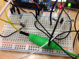
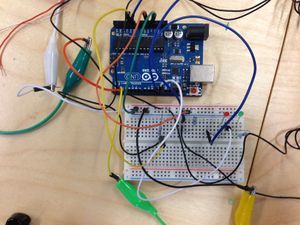
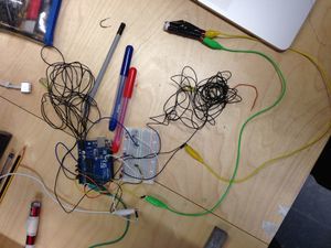
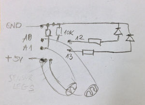
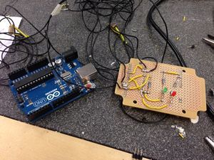
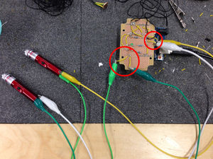
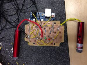
Once I had 1 laser & LDR set up and working with Arduino, I decided to add another laser. Which became problematic in Arduino initially. I also decided to add 2 LEDs to make it easier for myself to check if everything was working as it should. I used 10 Ohm resistors for the for the LDR’s, and 3 Ohm resistors for the LEDs. It took a lot of moving things around and reconfiguring wires to get it them both working. To then transfer my circuit from a breadboard to a perf board, I drew out a simple schematic drawing. I used rows of pin to connect the circuit board directly to the Arduino. The first couple of wires I soldered were quite long, and this made them weaker because they started to bend. I decided to take them off and start again with my much smaller wires. I also didn’t solder the tips of the wires the first time, but when I did it made it so much easier. The lasers were connected to the board using crocodile clips, attached to wires that were soldered on. The problem with this is that the clips often came loose as they didn’t have much to attach too. But also the wires became weak and flimsy because they’re always bending. (RED CIRCLES INDICATE IN PHOTOS) I decided to wire the lasers directly to the board to make the connection stronger, but also less long wires made it easier to see what was going on. The last image shows an error that I received while trying to configure both LDRs. Looking online and trial & error solved the problem.
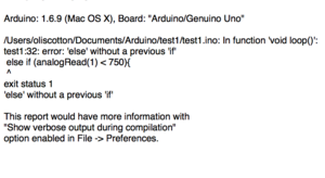
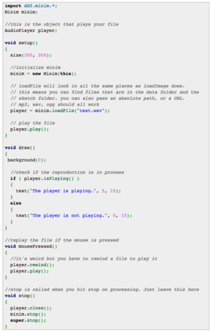
The first images shows the Arduino code used (taken from ‘Arduino Laser Tripwire’ tutorial referenced earlier.) I needed to use Processing along side Arduino to make sounds played when the laser is intercepted. I’d never used Processing before so it was something knew again, but there seemed to be a lot of information online about it. I spent a lot of time trying various code to get my Arduino to interactive with Processing. Pictures show examples. This is the code I first tried. — > [4] The problem seemed to be, connecting Arduino with Processing. I kept getting error in my Arduino code, such as "error: arduino was not declared in this scope”. I read on a forum that sometimes minim doesn’t work well on the latest version of Processing. So I downloaded version 1.5 but it wouldn’t run on my mac. Instead of minim, a lot of people suggested Firmata. It’s already installed into Arduino’s examples, so you can just open it inside the program. The difference is, with Firmata you upload all of the code onto the Arduino board, but then use processing to do the programming. I also ran into various problems with this. I read through countless forums to find an answer button couldn’t work it out. Some of the resources used —> [5] [6] [7]
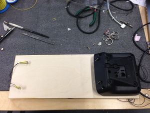
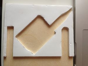
I decided to make some kind of housing for the board and something to hide the wires. I laser cut a piece thing board, and then found a plastic casing from the back of a speaker that I would use to cover everything. I would then run the wires of the LDR underneath the board, onto the other side. I ran out of time mounting everything as I wanted because I spent so much time trying to get the sounds to play from computer.
What I'd do if I had more time:
If I had more time work on my project, I would make sure I could get sound to play for a start. I planned to assign a different 808 drum sample to each laser-trip, this could also then be changed to chords from different instruments. The piece that I presented didn't utilise the ability to work on a further distance. It would require me using batteries in the lasers so that they could be place far away from the LDRs. I could have then made the sounds happen once someone walks past, making it more interactive. I'd also add maybe another lasers, so that users could use different body parts to make the sounds as they'd be spread further apart. I'd also like to play with the idea of doing this in a pitch black room, so the user can only see the dots from the laser, but then come to realise that if they block them, it'll make sounds. Overall i'm satisfied with my outcome although I wish I could have finished it. I've learn how to use Arduino and how to make a circuit board, so I'm really happy with my progress in this project.
VIDEO TESTS & EXPERIMENTATION! --> [8] [9]
Mimicking Machines
Assignment 1
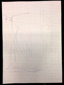
I Draw. You Draw. It Draws I decided to choose a kettle for my machine. I found an image online, then traced it using the Pen Tool on Adobe Illustrator. Once I had the vector outline, I placed a grid on top of the drawing, and then plotted indices across each side. Rather than using x & y with numbers, I decided to use letters across the top, and numbers down the side. Because the grid was wider than 26 points, I decided to use upper and lowercase letters. Although I thought it was clear enough to understand, it did cause some confusion to the user when presented with the instructions. I also decided to tell the user to 'DRAW LINE FROM CENTRE OF EACH SQUARE' because I thought it would have been too complex otherwise. The person trying to re-draw my machine got confused initially with the upper and lowercase letters, but once they had worked that out, they drew my machine just as I wanted.
Assignment 2
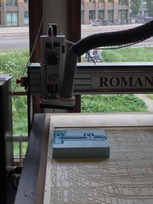
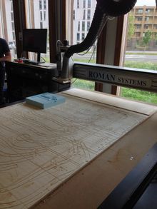
The Extruded Milled and Sliced Alphabet
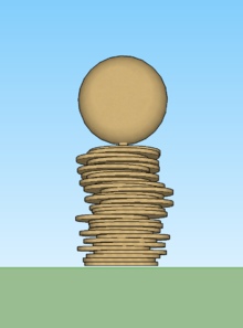
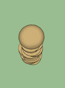
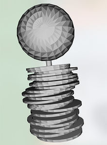
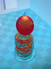
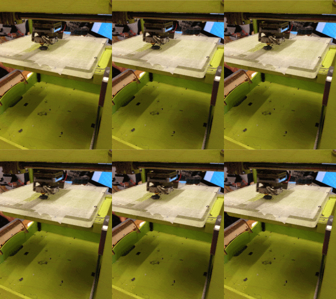
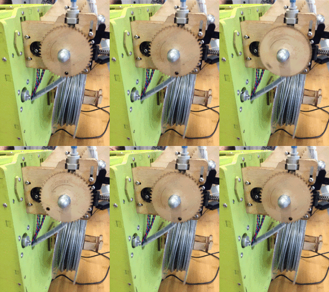
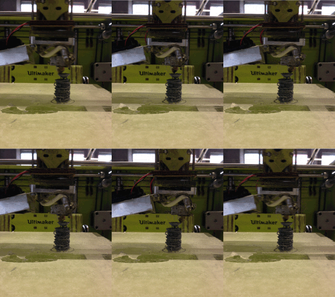
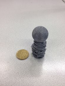
The 'I' I made was made from flat circular discs staked on top of each other, then a sphere on top attach by a small support in the centre. The shape I made was too large, so we scaled it down to 5cm in height. After this we had to decide wether it needed a support when printing, which it did. So we placed the shape vertically, because this way it needed less support material, which in return takes less time. It took a few goes to make sure the printer was calibrated correctly, and that it had enough space between the base and the extruder to print correctly. Because it's a small intricate model, it's hard to know what is the support material, and what isn't. Although it isn't exactly how I design it, I like the way the bottom half looks with the rough, pointy edges.
Assignment 3
""Human Powered Machine""

