Difference between revisions of "User:MickeyNerrings"
| (39 intermediate revisions by the same user not shown) | |||
| Line 9: | Line 9: | ||
Hi there, welcome on Mickey's page. | Hi there, welcome on Mickey's page. | ||
| − | Axel Verwee and I are working together. But of course we have our own pages. On mine you can find the work were I'm focussing on. :) | + | Axel Verwee and I are working together. But of course we have our own pages. On mine you can find the work were I'm focussing on, that will be the technical part. :) |
| Line 18: | Line 18: | ||
So we were the Electrons, we made a short dance out of it. '+ and -' came together and started to shake, because we were excited for being together. But when '- and -' came together they would clash. | So we were the Electrons, we made a short dance out of it. '+ and -' came together and started to shake, because we were excited for being together. But when '- and -' came together they would clash. | ||
| − | [[File:IMG_2134_2.JPG| | + | [[File:IMG_2134_2.JPG|200px]] |
| Line 24: | Line 24: | ||
Lab1 '''Measuring Voltage''' | Lab1 '''Measuring Voltage''' | ||
–––––––––––––––––––––––––––––––––––––––––––––––––––––––––––––––––––––––––––––––––––––––––––––––––––––––––––––––––––––––––––––––––––––––––––––––––––––––––––––––––––––––– | –––––––––––––––––––––––––––––––––––––––––––––––––––––––––––––––––––––––––––––––––––––––––––––––––––––––––––––––––––––––––––––––––––––––––––––––––––––––––––––––––––––––– | ||
| − | [[File:7.jpg| | + | [[File:7.jpg|200px]] |
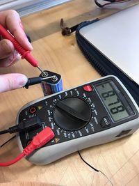
So we measured the Voltage, but we switched the + and - cables so we had a negative number. | So we measured the Voltage, but we switched the + and - cables so we had a negative number. | ||
| + | Voltage 8.87 | ||
–––––––––––––––––––––––––––––––––––––––––––––––––––––––––––––––––––––––––––––––––––––––––––––––––––––––––––––––––––––––––––––––––––––––––––––––––––––––––––––––––––––––– | –––––––––––––––––––––––––––––––––––––––––––––––––––––––––––––––––––––––––––––––––––––––––––––––––––––––––––––––––––––––––––––––––––––––––––––––––––––––––––––––––––––––– | ||
| Line 35: | Line 36: | ||
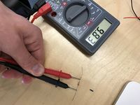
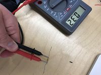
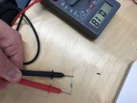
Here we measured the resister. You can see we had a resist of 0,78. | Here we measured the resister. You can see we had a resist of 0,78. | ||
| − | [[File:Resister1.JPG| | + | [[File:Resister1.JPG|200px]] [[File:Resister2.JPG|200px]] [[File:Resister3.JPG|200px]] |
| − | [[File:Resister2.JPG| | + | |
| − | [[File:Resister3.JPG| | + | Volt 1th restitor 9.83 Volt / 2nd 0.32 Volt / 3th 0.18 Volt/ 1th + 2nd together 10.15 Volt / 2nd + 3th together 0,5 Volt / 1th +2nd +3th together 10.83 |
| + | |||
| + | I = V/R | ||
| + | 9,11: 9,83 = 0,93 | ||
| + | 9,11 : 10.83 = 0,84 | ||
I measured different resisters so now I know the value. | I measured different resisters so now I know the value. | ||
| Line 43: | Line 48: | ||
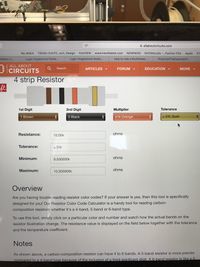
After that I put the resister information on the computer and calculate them. | After that I put the resister information on the computer and calculate them. | ||
| − | [[File:resistercom1.JPG| | + | [[File:resistercom1.JPG|200px]] [[File:resistercom2.JPG|200px]] [[File:resistercom3.JPG|200px]] |
| − | [[File:resistercom2.JPG| | ||
| − | [[File:resistercom3.JPG| | ||
Because I did it on my own it was difficult to understand. But I think it was interesting to figure this out. | Because I did it on my own it was difficult to understand. But I think it was interesting to figure this out. | ||
| Line 53: | Line 56: | ||
Lab1 '''Series resistance''' | Lab1 '''Series resistance''' | ||
–––––––––––––––––––––––––––––––––––––––––––––––––––––––––––––––––––––––––––––––––––––––––––––––––––––––––––––––––––––––––––––––––––––––––––––––––––––––––––––––––––––––– | –––––––––––––––––––––––––––––––––––––––––––––––––––––––––––––––––––––––––––––––––––––––––––––––––––––––––––––––––––––––––––––––––––––––––––––––––––––––––––––––––––––––– | ||
| − | [[File:serieresister1.JPG| | + | [[File:serieresister1.JPG|200px]] [[File:serieresister2.JPG|200px]] [[File:serieresister3.JPG|200px]] |
| − | [[File:serieresister2.JPG| | ||
| − | [[File:serieresister3.JPG| | ||
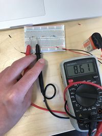
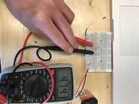
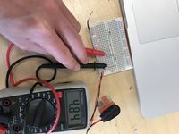
1.00 G - 10.00 k - 330.00 was showed on the website | 1.00 G - 10.00 k - 330.00 was showed on the website | ||
| Line 63: | Line 64: | ||
Lab1 '''Parallel resistance''' | Lab1 '''Parallel resistance''' | ||
–––––––––––––––––––––––––––––––––––––––––––––––––––––––––––––––––––––––––––––––––––––––––––––––––––––––––––––––––––––––––––––––––––––––––––––––––––––––––––––––––––––––– | –––––––––––––––––––––––––––––––––––––––––––––––––––––––––––––––––––––––––––––––––––––––––––––––––––––––––––––––––––––––––––––––––––––––––––––––––––––––––––––––––––––––– | ||
| − | [[File:Parallelresistance1.JPG| | + | [[File:Parallelresistance1.JPG|200px]] [[File:Parallelresistance2.JPG|200px]] [[File:Parallelresistance3.JPG|200px]] [[File:Parallelresistance4.JPG|200px]] |
| − | [[File:Parallelresistance2.JPG| | ||
| − | [[File:Parallelresistance3.JPG| | ||
| − | [[File:Parallelresistance4.JPG| | ||
When I measured the same resisters it gave me a difference of 0,10. The third resister gave me a number of 0.47. That the one from 470 Ohm | When I measured the same resisters it gave me a difference of 0,10. The third resister gave me a number of 0.47. That the one from 470 Ohm | ||
| Line 97: | Line 95: | ||
When I did the parallel circuit the led finally switched on. I didn't do something different then before so its a big question mark. It was the same led as before in the series circuit. | When I did the parallel circuit the led finally switched on. I didn't do something different then before so its a big question mark. It was the same led as before in the series circuit. | ||
But again the measurement tool gave me 00.0 voltage. I think this thing doesn't like me or something. Really weird. It is a bit disappointing because I find it hard to figure everything out. | But again the measurement tool gave me 00.0 voltage. I think this thing doesn't like me or something. Really weird. It is a bit disappointing because I find it hard to figure everything out. | ||
| + | |||
| + | |||
| + | |||
| + | –––––––––––––––––––––––––––––––––––––––––––––––––––––––––––––––––––––––––––––––––––––––––––––––––––––––––––––––––––––––––––––––––––––––––––––––––––––––––––––––––––––––– | ||
| + | Lab3 '''Making a Cricuit''' | ||
| + | –––––––––––––––––––––––––––––––––––––––––––––––––––––––––––––––––––––––––––––––––––––––––––––––––––––––––––––––––––––––––––––––––––––––––––––––––––––––––––––––––––––––– | ||
| + | |||
| + | So we had to make a own circuit. With a kinda touching patch. When we touch the pad it would give a sound. | ||
| + | |||
| + | First we tried to get the system printed on the coper plate. That worked very well. | ||
| + | |||
| + | [[File:6.jpg|400px|thumb|left]] [[File:Tab32.jpg|400px]] | ||
| + | |||
| + | |||
| + | |||
| + | [[File:18553766 10212410506073479 1557505576 o.jpg|200px]] [[File:Pro2.JPG|200px]] [[File:Pro3-min.JPG|200px]] | ||
| + | |||
| + | After the printing we tried to make the circuit. So, we attached al the resisters to the copper plate. Then we attached al the wires with the bug. The funniest thing about the circuit is that we choose one of the 4. But then I saw that they were the same as al the others. Only in a different order. | ||
| + | |||
| + | [[File:Tab31.jpg|400px]] | ||
| + | |||
| + | I tried to upload a video, but it didn't work. | ||
| + | |||
–––––––––––––––––––––––––––––––––––––––––––––––––––––––––––––––––––––––––––––––––––––––––––––––––––––––––––––––––––––––––––––––––––––––––––––––––––––––––––––––––––––––– | –––––––––––––––––––––––––––––––––––––––––––––––––––––––––––––––––––––––––––––––––––––––––––––––––––––––––––––––––––––––––––––––––––––––––––––––––––––––––––––––––––––––– | ||
| Line 117: | Line 138: | ||
''''''Feel My hotspot poster'''''' | ''''''Feel My hotspot poster'''''' | ||
–––––––––––––––––––––––––––––––––––––––––––––––––––––––––––––––––––––––––––––––––––––––––––––––––––––––––––––––––––––––––––––––––––––––––––––––––––––––––––––––––––––––– | –––––––––––––––––––––––––––––––––––––––––––––––––––––––––––––––––––––––––––––––––––––––––––––––––––––––––––––––––––––––––––––––––––––––––––––––––––––––––––––––––––––––– | ||
| + | [[File:poster111hotspot.jpg|400px|thumb|middle]] | ||
| + | |||
| + | Axel and I spoke to each other and decided to make our project a bit easier. Because otherwise it wouldn't be finished on time. | ||
| + | |||
| + | So our new concept is that people on festivals will wear a bracelet with a chip and one with a sensor (check in system). When people are buying tickets for the festival they have to give their top | ||
| + | three location and Facebook profile. This will be connected with a chip they will get at the festival. When you are interested in someone, you just check in on their bracelet. Well of course if they accept you. | ||
| + | When they accept you, the chip wil send your information to the email address from the other person. So then you don't need phone on he festival. Also it's a nice idea to find each other back in real life after the festival. | ||
| + | |||
| + | |||
| + | |||
| + | |||
| + | |||
| + | |||
| + | –––––––––––––––––––––––––––––––––––––––––––––––––––––––––––––––––––––––––––––––––––––––––––––––––––––––––––––––––––––––––––––––––––––––––––––––––––––––––––––––––––––––– | ||
| + | ''''''The system'''''' | ||
| + | –––––––––––––––––––––––––––––––––––––––––––––––––––––––––––––––––––––––––––––––––––––––––––––––––––––––––––––––––––––––––––––––––––––––––––––––––––––––––––––––––––––––– | ||
| + | |||
| + | So I decided to work with RaspberryPi. | ||
| + | First of all I needed to instal a couple of programs on the Raspberry Pi. That was already a challenge. But with some tutorials on youtube it worked out perfectly. | ||
| + | |||
| + | I had to create a code to send an email from the raspberry pi to my email. So I needed a screen, keyboard and also a mouse and an internet cable. After I found all those things I tried to create a code for sending an email. First I looked on the internet for basic codes, then I had to adjust them and fill in the correct information. For example, the sender and receiver emails. After I had the code I thought it would work. | ||
| + | |||
| + | [[File:Mail1.jpg|300px|]] This was the code that didn't work out. | ||
| + | |||
| + | But it didn't. So I tried a new code. The problem was that I needed an extra code that I couldn't know. So Thomas a instructor helped me with that. | ||
| + | |||
| + | So after a couple of times it finally worked out. | ||
| + | |||
| + | [[File:Raspberrypi.JPG|300px|]] [[File:mail.jpg|300px|middle]] Using Python for creating the email code | ||
| + | Finally I could connect it with my school email! :D This is awesome. | ||
| + | |||
| + | |||
| + | The next step was to connect a sensor with the raspberry pi, and a chip that would activate a code that would send a email. | ||
| + | The first things I had to do: get a sensor and a chip. then find a code and that was it. Well I thought that was it. Because after I connected the sensor with the Raspberry Pi I noticed that it didn't work. | ||
| + | |||
| + | [[File:Sensor13.JPG|300px|]] [[File:aansluiting2.JPG|300px|]] | ||
| + | |||
| + | The problem was that I needed an other small system that would work as receiver of the sensor. This would send information to the Raspberry Pi. So I needed a breadboard and resisters and some wires. | ||
| + | |||
| + | [[File:aansluiting.JPG|300px|]] [[File:aansluiting3.JPG|300px|]] [[File: okokok.png|300px|thumb|left|alt text]] | ||
| + | |||
| + | I wanted to connect the new small green board with a breadboard. Then let it work, but I needed to know the meaning of the pins on the raspberry pi. So I found a map, that explained the pins. I mentioned that the pin with 5V had to be connected with the breadboard. I used a resistor for that, because other wise I could create a to strong loop. | ||
| + | |||
| + | So when the sensor was working with the check-in chips I had to name them. | ||
| + | |||
| + | [[File:code1111.JPG|300px|]] | ||
| + | |||
| + | The yellow chips had to be coded as we, so I used 3 of them. All 3 with different names. That was easy to do, but the problem with the check ins was that it constantly could check-in the one that already was checked-in. So I tried to block them, that they can't check-in if they already are. | ||
| + | |||
| + | I used in the code: If inlognummer ==13 (''nummer13'') To number them. So i created different numbers. | ||
| + | |||
| + | I connected the chip with some emailadressen, in a really easy way. Combined the codes together and made a logical structure. | ||
| + | |||
| + | So what then happend was really cool, because when I moved the chip around the sensor it send a email to my email account. | ||
| + | |||
| + | I put the test text in the mail code, so i could see if it worked, after that I put the correct lines in the code. The Raspberry Pi is now only adjust to electricity and internet. So for me this was a new challenge to get it all wireless. | ||
| + | |||
| + | [[File:Eduroam2.JPG|300px|]] | ||
| + | |||
| + | I tried a code that I found on the internet, and after that I adjust the information of the school network. Unfortunately that didn't work. | ||
| + | So I tried another code and that didn't work as well. After some research and talking with some teachers, it worked out. | ||
| + | |||
| + | [[File:Eduroam.JPG|300px|]] [[File:wifi.JPG|300px|]] | ||
| + | |||
| + | Making the Raspberry Pi run on a battery was pretty easy, I just used a powerbank, and replaced it for the electricity wire. A power bank must have 1100 mAh. | ||
| + | |||
| + | So here is the whole process of the technical part. And the research part. Hope you guys enjoyed it, and of course now I can tell you more about the Raspberry Pi. So If you have any questions, just ask. | ||
| + | |||
| + | |||
| + | –––––––––––––––––––––––––––––––––––––––––––––––––––––––––––––––––––––––––––––––––––––––––––––––––––––––––––––––––––––––––––––––––––––––––––––––––––––––––––––––––––––––– | ||
| + | '''Teamwork''' | ||
| + | –––––––––––––––––––––––––––––––––––––––––––––––––––––––––––––––––––––––––––––––––––––––––––––––––––––––––––––––––––––––––––––––––––––––––––––––––––––––––––––––––––––––– | ||
| + | |||
| + | We decided to make a team with Kaylee and Maxime. They made a table carpet, with light connection and mobile telephones. Really interesting and we thought we could make a good exposition together. We thought this was a nice project because we could combine the 2 projects in 1 presentation because people who get to know each other at a dinner or a picknic/festival can exchange information without picking up their phones and disconnecting with your dinner partners. | ||
| + | |||
| + | |||
| + | [[File:Samenwerk2.JPG|300px|]] [[File:Samenwerk1.JPG|300px|]] | ||
Latest revision as of 07:17, 22 June 2017
Name: Mickey Nerrings
e-mail: 0916054@hr.nl
Hi there, welcome on Mickey's page.
Axel Verwee and I are working together. But of course we have our own pages. On mine you can find the work were I'm focussing on, that will be the technical part. :)
––––––––––––––––––––––––––––––––––––––––––––––––––––––––––––––––––––––––––––––––––––––––––––––––––––––––––––––––––––––––––––––––––––––––––––––––––––––––––––––––––––––––
Lab0 Group exercise: You are the Electrons
––––––––––––––––––––––––––––––––––––––––––––––––––––––––––––––––––––––––––––––––––––––––––––––––––––––––––––––––––––––––––––––––––––––––––––––––––––––––––––––––––––––––
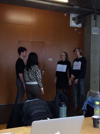
So we were the Electrons, we made a short dance out of it. '+ and -' came together and started to shake, because we were excited for being together. But when '- and -' came together they would clash.
––––––––––––––––––––––––––––––––––––––––––––––––––––––––––––––––––––––––––––––––––––––––––––––––––––––––––––––––––––––––––––––––––––––––––––––––––––––––––––––––––––––––
Lab1 Measuring Voltage
––––––––––––––––––––––––––––––––––––––––––––––––––––––––––––––––––––––––––––––––––––––––––––––––––––––––––––––––––––––––––––––––––––––––––––––––––––––––––––––––––––––––
So we measured the Voltage, but we switched the + and - cables so we had a negative number. Voltage 8.87
––––––––––––––––––––––––––––––––––––––––––––––––––––––––––––––––––––––––––––––––––––––––––––––––––––––––––––––––––––––––––––––––––––––––––––––––––––––––––––––––––––––––
Lab1 Measuring resistence
––––––––––––––––––––––––––––––––––––––––––––––––––––––––––––––––––––––––––––––––––––––––––––––––––––––––––––––––––––––––––––––––––––––––––––––––––––––––––––––––––––––––
Here we measured the resister. You can see we had a resist of 0,78.
Volt 1th restitor 9.83 Volt / 2nd 0.32 Volt / 3th 0.18 Volt/ 1th + 2nd together 10.15 Volt / 2nd + 3th together 0,5 Volt / 1th +2nd +3th together 10.83
I = V/R 9,11: 9,83 = 0,93 9,11 : 10.83 = 0,84
I measured different resisters so now I know the value.
After that I put the resister information on the computer and calculate them.
Because I did it on my own it was difficult to understand. But I think it was interesting to figure this out.
––––––––––––––––––––––––––––––––––––––––––––––––––––––––––––––––––––––––––––––––––––––––––––––––––––––––––––––––––––––––––––––––––––––––––––––––––––––––––––––––––––––––
Lab1 Series resistance
––––––––––––––––––––––––––––––––––––––––––––––––––––––––––––––––––––––––––––––––––––––––––––––––––––––––––––––––––––––––––––––––––––––––––––––––––––––––––––––––––––––––
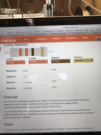
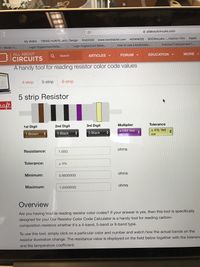
1.00 G - 10.00 k - 330.00 was showed on the website
What I measured: 8.61 - 4.74 - 4.84 I don't know why mine are so different. And I also did not understand how I could change it. ––––––––––––––––––––––––––––––––––––––––––––––––––––––––––––––––––––––––––––––––––––––––––––––––––––––––––––––––––––––––––––––––––––––––––––––––––––––––––––––––––––––––
Lab1 Parallel resistance
––––––––––––––––––––––––––––––––––––––––––––––––––––––––––––––––––––––––––––––––––––––––––––––––––––––––––––––––––––––––––––––––––––––––––––––––––––––––––––––––––––––––
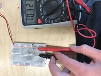
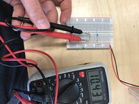
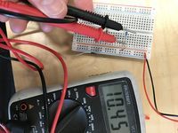
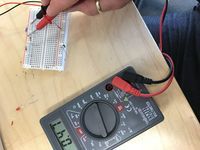
When I measured the same resisters it gave me a difference of 0,10. The third resister gave me a number of 0.47. That the one from 470 Ohm
––––––––––––––––––––––––––––––––––––––––––––––––––––––––––––––––––––––––––––––––––––––––––––––––––––––––––––––––––––––––––––––––––––––––––––––––––––––––––––––––––––––––
Lab1 Measuring Current
––––––––––––––––––––––––––––––––––––––––––––––––––––––––––––––––––––––––––––––––––––––––––––––––––––––––––––––––––––––––––––––––––––––––––––––––––––––––––––––––––––––––
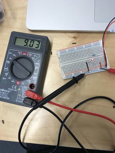
I measured the current with a voltage of 9.03 V
––––––––––––––––––––––––––––––––––––––––––––––––––––––––––––––––––––––––––––––––––––––––––––––––––––––––––––––––––––––––––––––––––––––––––––––––––––––––––––––––––––––––
Lab1 Measuring voltage and current in a series circuit
––––––––––––––––––––––––––––––––––––––––––––––––––––––––––––––––––––––––––––––––––––––––––––––––––––––––––––––––––––––––––––––––––––––––––––––––––––––––––––––––––––––––
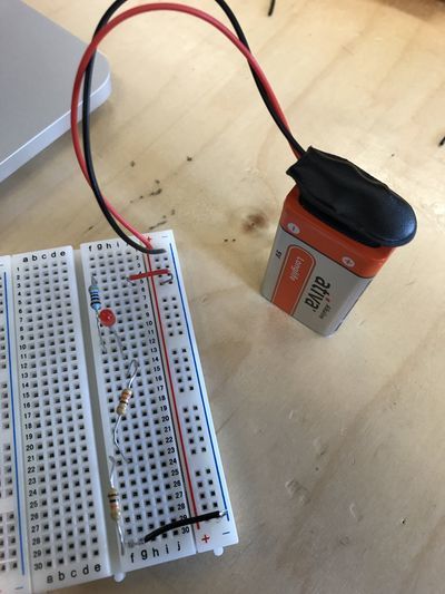
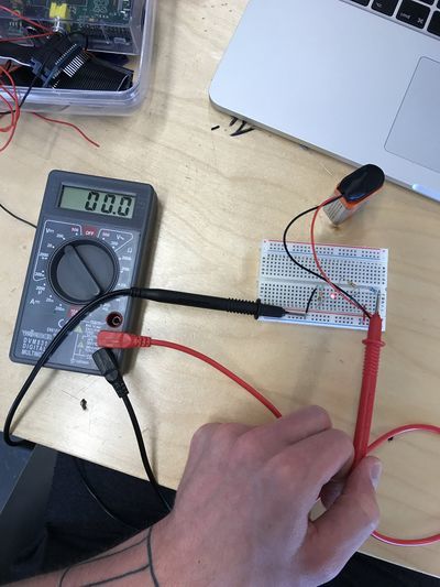
After I made the circuit and measured the battery on its own it didn't gave a reaction with the measurement tool. I tried different things but it was still giving me 0. The LED didn't even burn. I tried to get it solved. But everytime the measurementtool gave me 0. ––––––––––––––––––––––––––––––––––––––––––––––––––––––––––––––––––––––––––––––––––––––––––––––––––––––––––––––––––––––––––––––––––––––––––––––––––––––––––––––––––––––––
Lab1 Measuring voltage and current in a parallel circuit
––––––––––––––––––––––––––––––––––––––––––––––––––––––––––––––––––––––––––––––––––––––––––––––––––––––––––––––––––––––––––––––––––––––––––––––––––––––––––––––––––––––––
When I did the parallel circuit the led finally switched on. I didn't do something different then before so its a big question mark. It was the same led as before in the series circuit. But again the measurement tool gave me 00.0 voltage. I think this thing doesn't like me or something. Really weird. It is a bit disappointing because I find it hard to figure everything out.
––––––––––––––––––––––––––––––––––––––––––––––––––––––––––––––––––––––––––––––––––––––––––––––––––––––––––––––––––––––––––––––––––––––––––––––––––––––––––––––––––––––––
Lab3 Making a Cricuit
––––––––––––––––––––––––––––––––––––––––––––––––––––––––––––––––––––––––––––––––––––––––––––––––––––––––––––––––––––––––––––––––––––––––––––––––––––––––––––––––––––––––
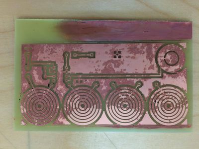
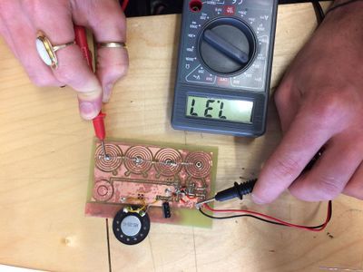
So we had to make a own circuit. With a kinda touching patch. When we touch the pad it would give a sound.
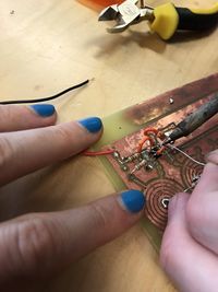
First we tried to get the system printed on the coper plate. That worked very well.
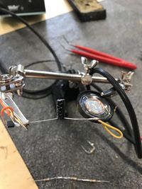
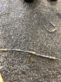
After the printing we tried to make the circuit. So, we attached al the resisters to the copper plate. Then we attached al the wires with the bug. The funniest thing about the circuit is that we choose one of the 4. But then I saw that they were the same as al the others. Only in a different order.
I tried to upload a video, but it didn't work.
––––––––––––––––––––––––––––––––––––––––––––––––––––––––––––––––––––––––––––––––––––––––––––––––––––––––––––––––––––––––––––––––––––––––––––––––––––––––––––––––––––––––
'Feel My hotspot'
––––––––––––––––––––––––––––––––––––––––––––––––––––––––––––––––––––––––––––––––––––––––––––––––––––––––––––––––––––––––––––––––––––––––––––––––––––––––––––––––––––––––
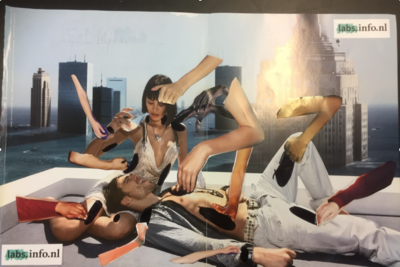
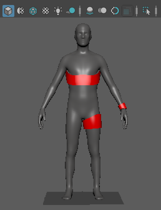
Well, we are creating a concept, its about how people can interact with each other if they met in a bar or somewhere else. The interaction is about touching. When you touch someone you could get some information about the person. For example, I meet someone nice in the bar, then I just touch his shoulder, and then a small censor will give a detail of information of that person. We will just start with a small detail like: Where does he go out sometimes? That location will be open for me to see. Only if the other person is interested to. On that point we can go further because if there is a connection. When we will meet up again we can touch each other on the arms for example and then i'll know what kind of work he does. And he also can accept it that i can see the location of his work.
After a long talk we decided that I had to make a more clear image then the one above. So I focused myself on a 3D sculpture in Maya. There I made a human form and try to look for the correct places.
––––––––––––––––––––––––––––––––––––––––––––––––––––––––––––––––––––––––––––––––––––––––––––––––––––––––––––––––––––––––––––––––––––––––––––––––––––––––––––––––––––––––
'Feel My hotspot poster'
––––––––––––––––––––––––––––––––––––––––––––––––––––––––––––––––––––––––––––––––––––––––––––––––––––––––––––––––––––––––––––––––––––––––––––––––––––––––––––––––––––––––
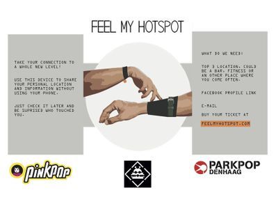
Axel and I spoke to each other and decided to make our project a bit easier. Because otherwise it wouldn't be finished on time.
So our new concept is that people on festivals will wear a bracelet with a chip and one with a sensor (check in system). When people are buying tickets for the festival they have to give their top three location and Facebook profile. This will be connected with a chip they will get at the festival. When you are interested in someone, you just check in on their bracelet. Well of course if they accept you. When they accept you, the chip wil send your information to the email address from the other person. So then you don't need phone on he festival. Also it's a nice idea to find each other back in real life after the festival.
––––––––––––––––––––––––––––––––––––––––––––––––––––––––––––––––––––––––––––––––––––––––––––––––––––––––––––––––––––––––––––––––––––––––––––––––––––––––––––––––––––––––
'The system'
––––––––––––––––––––––––––––––––––––––––––––––––––––––––––––––––––––––––––––––––––––––––––––––––––––––––––––––––––––––––––––––––––––––––––––––––––––––––––––––––––––––––
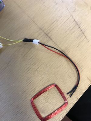
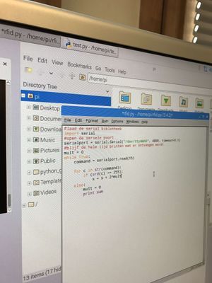
So I decided to work with RaspberryPi. First of all I needed to instal a couple of programs on the Raspberry Pi. That was already a challenge. But with some tutorials on youtube it worked out perfectly.
I had to create a code to send an email from the raspberry pi to my email. So I needed a screen, keyboard and also a mouse and an internet cable. After I found all those things I tried to create a code for sending an email. First I looked on the internet for basic codes, then I had to adjust them and fill in the correct information. For example, the sender and receiver emails. After I had the code I thought it would work.
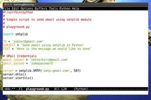 This was the code that didn't work out.
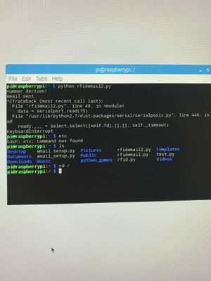
But it didn't. So I tried a new code. The problem was that I needed an extra code that I couldn't know. So Thomas a instructor helped me with that.
So after a couple of times it finally worked out.
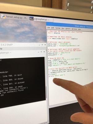
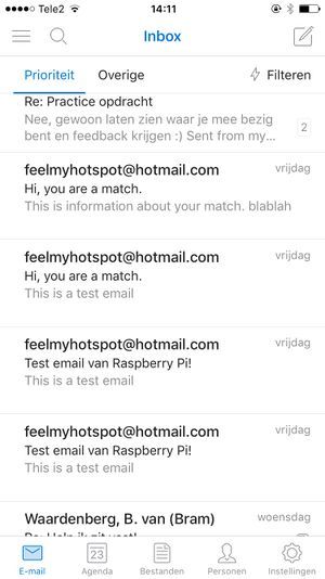 Using Python for creating the email code
Finally I could connect it with my school email! :D This is awesome.
The next step was to connect a sensor with the raspberry pi, and a chip that would activate a code that would send a email.
The first things I had to do: get a sensor and a chip. then find a code and that was it. Well I thought that was it. Because after I connected the sensor with the Raspberry Pi I noticed that it didn't work.
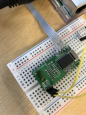
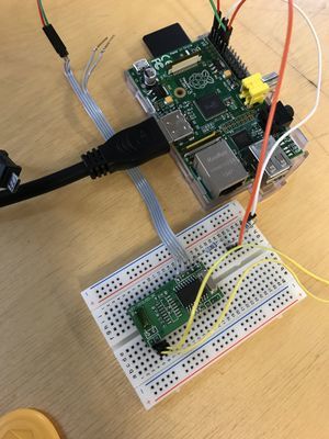
The problem was that I needed an other small system that would work as receiver of the sensor. This would send information to the Raspberry Pi. So I needed a breadboard and resisters and some wires.
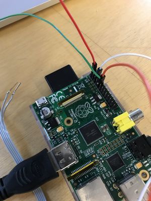
I wanted to connect the new small green board with a breadboard. Then let it work, but I needed to know the meaning of the pins on the raspberry pi. So I found a map, that explained the pins. I mentioned that the pin with 5V had to be connected with the breadboard. I used a resistor for that, because other wise I could create a to strong loop.
So when the sensor was working with the check-in chips I had to name them.
The yellow chips had to be coded as we, so I used 3 of them. All 3 with different names. That was easy to do, but the problem with the check ins was that it constantly could check-in the one that already was checked-in. So I tried to block them, that they can't check-in if they already are.
I used in the code: If inlognummer ==13 (nummer13) To number them. So i created different numbers.
I connected the chip with some emailadressen, in a really easy way. Combined the codes together and made a logical structure.
So what then happend was really cool, because when I moved the chip around the sensor it send a email to my email account.
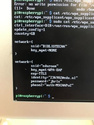
I put the test text in the mail code, so i could see if it worked, after that I put the correct lines in the code. The Raspberry Pi is now only adjust to electricity and internet. So for me this was a new challenge to get it all wireless.
I tried a code that I found on the internet, and after that I adjust the information of the school network. Unfortunately that didn't work. So I tried another code and that didn't work as well. After some research and talking with some teachers, it worked out.
Making the Raspberry Pi run on a battery was pretty easy, I just used a powerbank, and replaced it for the electricity wire. A power bank must have 1100 mAh.
So here is the whole process of the technical part. And the research part. Hope you guys enjoyed it, and of course now I can tell you more about the Raspberry Pi. So If you have any questions, just ask.
––––––––––––––––––––––––––––––––––––––––––––––––––––––––––––––––––––––––––––––––––––––––––––––––––––––––––––––––––––––––––––––––––––––––––––––––––––––––––––––––––––––––
Teamwork
––––––––––––––––––––––––––––––––––––––––––––––––––––––––––––––––––––––––––––––––––––––––––––––––––––––––––––––––––––––––––––––––––––––––––––––––––––––––––––––––––––––––
We decided to make a team with Kaylee and Maxime. They made a table carpet, with light connection and mobile telephones. Really interesting and we thought we could make a good exposition together. We thought this was a nice project because we could combine the 2 projects in 1 presentation because people who get to know each other at a dinner or a picknic/festival can exchange information without picking up their phones and disconnecting with your dinner partners.

