Difference between revisions of "User:Paulacruz"
| Line 14: | Line 14: | ||
=== Feedbacks === | === Feedbacks === | ||
| − | 09/06 | | + | 09/06 | Thinking about some kind of interaction > touch circuits. For next week: have some tests with the conductive materials. Remember to use a cheap pen knife when cutting the conductive tape. |
| + | |||
| + | List of materials and tips: | ||
| + | * [https://www.conrad.nl/nl/pb-fastener-zelfklevende-koperfolie-l-x-b-150-mm-x-30-mm-529532.html PB Fastener Koperfolie 150mm x 30mm] | ||
| + | * [http://www.techsoft.co.uk/products/knife-cutting/materials/cutronic-foil-pcbs.asp Cutronic foil for PCBS] | ||
| + | * Aluminium tape at HEMA (for testing circuits) | ||
| + | * [http://www.kobakant.at/DIY/ How to get waht you want] | info in general for my project | ||
| + | * [http://www.kobakant.at/DIY/?p=2176 Conductive Copper Tape] | ||
| + | * [http://www.kobakant.at/DIY/?p=1132 Using a vinyl cutter to cut the traces of a circuit design out of copper foil with adhesive backing] | ||
| + | * Bare conductive ink | ||
| + | * Conductive nickel pen | ||
=== Progress === | === Progress === | ||
Revision as of 11:35, 9 June 2015
Contents
P R O J E C T ☺
After searching for references and inspiration, I've decided to design a paper circuit. Using The great big guide to paper circuits, I will create a typograhic poster with conductive tape or conductive ink (working with conductive carbon graphite powder is also possible, but probably less practical to attach components). I'm also planning to play around with LEDs and lights in the circuit/poster. I have in mind not only to experiment with form and typography, but also with circuits. Thus, I can unite my major (graphic design) with this practice (digital craft) in this project.
Main inspirations
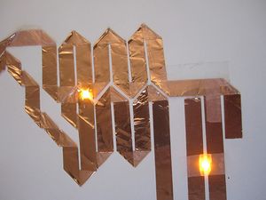
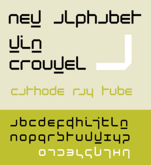
I've came up with this idea after finding an image of conductive tape folded in a circuit, which reminds me the New Alphabet of Wim Crouwel [1], a Dutch graphic designer, type designer, and typographer know for his experiments on typography and readability. My plan is to design the circuit and the typeface with LEDs on it. I still have to came up with a sentence or a word for the poster.
- From 1964 onwards, Crouwel was responsible for the design of the posters, catalogues and exhibitions of the Stedelijk Museum in Amsterdam. In 1967 he designed the typeface New Alphabet, a design that embraces the limitations of the cathode ray tube technology used by early data display screens and phototypesetting equipment, thus only containing horizontal and vertical strokes.
Feedbacks
09/06 | Thinking about some kind of interaction > touch circuits. For next week: have some tests with the conductive materials. Remember to use a cheap pen knife when cutting the conductive tape.
List of materials and tips:
- PB Fastener Koperfolie 150mm x 30mm
- Cutronic foil for PCBS
- Aluminium tape at HEMA (for testing circuits)
- How to get waht you want | info in general for my project
- Conductive Copper Tape
- Using a vinyl cutter to cut the traces of a circuit design out of copper foil with adhesive backing
- Bare conductive ink
- Conductive nickel pen
Progress
Under construction! :)
P E R S O N A L ∴ I N S P I R A T I O N
T U T O R I A L S & H E L P
- Como interpretar diagramas [[1]]
- Como ler esquema eletrônico, eletrônica, eletricidade, circuito impresso, fenolite [[2]]
- 3x3x3 LED Cube Circuit [[3]]
- Getting started with copper tape for paper electronics [video] [[4]]
- High-low [list of good tutorials] [[5]]
- A quick tutorial on diluting eletric paint [[6]]
- Stencil graphic with a vinyl stencil [[7]]
H O M E W O R K S
Homework 01 | Understanding electronic circuits
Circuit with one resistor | Battery 6.73V | Resistor 471 Ohm
Voltage across resistor 6,1 V | Current through resistor 12,9 A
↳ Double resistor (1k)
Voltage 6,35 V | Current 6,4 A
↳ Half Resistor (220 Ohms)
Voltage 5,5 V | Current 25,2 A
Circuit with two resistors | Battery 6,7 V | Resistors 470 Ohm
Voltage across resistor ¹ 3,2V Current resistor ¹ 6,8 A
Voltage across resistor ² 3,2V Current resistor ² 6,8 A
↳ Double one of them | Battery 6,7 V | Resistor 470 Ohm and 940 Ohm
Voltage resistor ¹ (double) 4,4 V Current resistor ¹ (double) 4,4 A
Voltage resistor ² 2,05 V Current resistor ² 4,4 A
↳ Half Value of resistor | Battery 6,7 V | Resistor 470 Ohm and 220 Ohm
Voltage resistor ¹ 2,05 V Current resistor ¹ (half): 9,2 A
Voltage resistor ² 4,25 V Current resistor ² 9,2A
Circuit with four resistors | Battery 6,5 V | Fours resistor of 470 Ohms (total of 1410 Ohms)
Voltage across all resistors 1,6 V Current across all resistors 3,5 A
↳ Double one of them
Voltage resistor double 2,7V | Voltage resistor rest 1,27V | Current 2,7A
↳ Half Value of resistor
Current 4 A
Voltage resistor half 0,87 V Voltage resistor rest 1,87 V
Two parallel | Battery 6,4 V | Resistor 470 Ohms
Voltage resistors 5,7V Current both 12,2 A
↳ Double resistor
Voltage normal 5,85 V Voltage double 5,85 V
Current normal 12,5 A Current double 5,9 A
↳ Half resistor
Voltage half 5,36 Voltage normal 5,36
Current normal 11,5 A Current half 24,5 A
Three parallel | Battery 6,3 V | Resistors 470 Ohms
Voltage resistors: 5,5V Current 12,9 A
↳ Double resistor
Voltage 5,6 V
Current double 6,3 A Current normal 12,9 A
↳ Half resistor
Voltage 5,16 V
Current half 23,3 A Current normal 10,7 A
LED lamp
Less resistance ⟿ more light
Homework 02 | To find and build a (small) circuit using the 555 timer
A Circuit that flashes an LED on and off. [[8]]
↳ This circuit uses the 555 timer in an Astable operating mode which generates a continuous output via Pin 3 in the form of a square wave. This turns the LED (D1) on and off. The speed at which the LED (D1) is turned on and off is set by the values of R1 and R2.
Parts lists
1x - NE555 Bipolar Timer
1x - LED (Red)
1x - 470K Resistor (1/4W)
2x - 1K Resistor (1/4W)
1x - 1μF Electrolytic Capacitor (16V)
1x - 9V Voltage Battery
Comments and observations
- Smaller resistors led into faster flashing lights.
- To add more LEDs, it is needed to create a "bridge" (using wire).
- More LEDs will use more of the battery. You need to check out the value of the battery before adding LEDs. Adding LEDs to the circuit may overload the 555 Timer. In order to avoid it, it should be add more resistors in the circuit.
Homework 03 | Recreating schematic layout
1. Download and install CadSoft EAGLE
2. Download the EAGLE 555 blink template with schematic and PCB layer here: Media:Eagle_555_template.zip .
3. The template contains all the components needed to create a simple 555 Astable circuit (aka a Blinking LED)
4. Create the PCB layout
5. Following the SparkFun tutorials on EAGLE (see resources below) will be VERY helpful along the way!!
6. Don't not make your PCB larger than 3 x 3 cm (as in the template).
7. Don't make your traces smaller than ~0.3mm (12mil)


