Difference between revisions of "User:Sneha Arvind"
Sneha Arvind (talk | contribs) (→Lab2) |
Sneha Arvind (talk | contribs) (→Lab2) |
||
| Line 28: | Line 28: | ||
[[File:Photo froo Sneha Arvind.jpg|200px|]] | [[File:Photo froo Sneha Arvind.jpg|200px|]] | ||
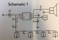
| + | Schematic Diagram | ||
<gallery mode="packed"> | <gallery mode="packed"> | ||
| Line 33: | Line 34: | ||
File:IMAG3977.jpeg | File:IMAG3977.jpeg | ||
File:IMAG3980.jpg | File:IMAG3980.jpg | ||
| + | </gallery> | ||
| − | + | '''Process''' | |
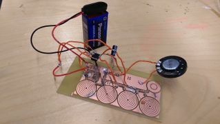
| − | + | 1. Etch the schematic diagram onto the copper plate. For this, I printed the schematic diagram onto the copper place first and then dipped it in acid to get etched.Time duration included 1 1/2 hours. | |
Revision as of 00:46, 15 June 2017
Hello! Welcome to my page!
Name : Sneha Arvind Email : 0941442@hr.nl
Department - Spatial Design \ Q8
Contents
Group Exercise
Group Members - Sneha Arvind Shipra Balasubramani Mirdu Jhangiani Niko Arranz Aayushi Katare
In this exercise, each group had to present a concept learnt on that day in a creative way with an aim to break it down for students to understand. Our group presented the influence of a 'resistor' on the working of a circuit. In the absence of the resistor, the bulb of the circuit fuses due to excess current flowing through the circuit. The excess current results in heating. In the presence of the resistor, current is regulated thus making the bulb glow. The other elements of the circuit include Shipra as the resistor, Aayuhi as the key, Niko as the battery, Mridu as the electrons in motion and myself, Sneha as the bulb.
LABS
Lab 1
Measuring Voltage, Current and Resistance
Lab2
Principle - The voltage at the different resistors gets converted to sound
- IMAG3977.jpeg
Process 1. Etch the schematic diagram onto the copper plate. For this, I printed the schematic diagram onto the copper place first and then dipped it in acid to get etched.Time duration included 1 1/2 hours.


