Difference between revisions of "User:Kayl"
| Line 165: | Line 165: | ||
–––––––––––––––––––––––––––––––––––––––––––––––––––––––––––––––––––––––––––––––––––––––––––––––––––––––––––––––––––––––––––––––––––––––––––––––––––––––––––––––––––––––– | –––––––––––––––––––––––––––––––––––––––––––––––––––––––––––––––––––––––––––––––––––––––––––––––––––––––––––––––––––––––––––––––––––––––––––––––––––––––––––––––––––––––– | ||
| − | In the third class we had to make a Keyboard. in this assignment we could show what we have learned about circuits with resistors and LEDs, and about measuring voltage. we also learned new things about how to adjust a copper plate, and how to solder a microchip. First we picked a schematic. Axel Verwee and I had schematic 1 so we teamed up for this assignment. We had to draw the circuit on a copper plate. Ad first we tried to iron a image on the copper. this only worked for half of the image. Then we grinded our version of the schematic on the copper plate. The soldering of the chip was the hardest part, this went wrong the first time as the paws of the chip broke when we tried to attach the treads to other componends. | + | [[File:Image-2017-06-21_(4).jpg|200px|thumb|Image after ironing a wet print of a circuit on a copper plate and removing the paper]][[File: Image-2017-06-21_(5).jpg|200px|thumb|Image of copper plate after removing the rest of the paper with more water]][[File: Image-2017-06-21_(6).jpg|200px|thumb|grinding a schematic on the copper]][[File: IMG-20170518-WA0010.jpg|200px|thumb|Attaching the first componends to the copper plate]][[File: IMG-20170518-WA0012.jpg|200px|thumb|The first attampt to connect the microchip failed as a paw of the chip broke off]] |
| + | |||
| + | In the third class we had to make a Keyboard. in this assignment we could show what we have learned about circuits with resistors and LEDs, and about measuring voltage. we also learned new things about how to adjust a copper plate, and how to solder a microchip. First we picked a schematic. Axel Verwee and I had schematic 1 so we teamed up for this assignment. We had to draw the circuit on a copper plate. Ad first we tried to iron a printed image on the copper. if the ink would have sticked on the copper we could have put the copper in a gemecal bath but this only worked for half of the image. Then we grinded our version of the schematic on the copper plate. The soldering of the chip was the hardest part, this went wrong the first time as the paws of the chip broke when we tried to attach the treads to other componends and on the copper plate. The second time we first connected all the paws of the chip to other threads. then we soldered all the other componends on the copper plate, and at last we connected te threads from the chip to other parts on the plate untill everything was connected. We designed our keyboard in such a way that the chip was floating in the air. It was very nice to look at and it worked! you only had to hold the speaker up because we placed it upside down; the metal part under the speaker made contact to the copper plate which we could solve with a small piece of tape underneed the speaker. | ||
Revision as of 11:53, 21 June 2017
Expanded Toolbox 2017
17-04-2017
Kaylee Nieuwenhuizen
Welcome on my page. My name is Kaylee and my email is 0912721@hr.nl.
I will post about my proces of the digital craft minor 2017 Q8 - WDKA
––––––––––––––––––––––––––––––––––––––––––––––––––––––––––––––––––––––––––––––––––––––––––––––––––––––––––––––––––––––––––––––––––––––––––––––––––––––––––––––––––––––––
Contents
First Class: Group exercise 20-04-2017
––––––––––––––––––––––––––––––––––––––––––––––––––––––––––––––––––––––––––––––––––––––––––––––––––––––––––––––––––––––––––––––––––––––––––––––––––––––––––––––––––––––––
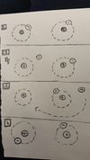
We are the Electrons. We learned that '+ and -' came together, in a dance we showed this with shaking our body but when '- and -' came together they would clash. How the Electrons react is explained further in the drawing that we made, on the left.
––––––––––––––––––––––––––––––––––––––––––––––––––––––––––––––––––––––––––––––––––––––––––––––––––––––––––––––––––––––––––––––––––––––––––––––––––––––––––––––––––––––––
No Class: Holidays 27-04-2017
––––––––––––––––––––––––––––––––––––––––––––––––––––––––––––––––––––––––––––––––––––––––––––––––––––––––––––––––––––––––––––––––––––––––––––––––––––––––––––––––––––––––
No Class: Hacking 04-05-2017
––––––––––––––––––––––––––––––––––––––––––––––––––––––––––––––––––––––––––––––––––––––––––––––––––––––––––––––––––––––––––––––––––––––––––––––––––––––––––––––––––––––––
Second Class: Measuring 11-05-2017
–––––––––––––––––––––––––––––––––––––––––––––––––––––––––––––––––––––––––––––––––––––––––––––––––––––––––––––––––––––––––––––––––––––––––––––––––––––––––––––––––––––––– In this class we started with a summary of the first class. In a battery the elektrons go from the + side to the - side. A Led light has a long and a short, the long side is the + side and is called Anode, the short side is the - side and is called Cathode. A resistor is to limit the presure of the battery for a Led light for example. A resistor = Ohm. You can calculate how much the resistor resists with a dutch"donkey bridge": Zij bracht rozen op gerrits graf bij vies grauw weer
1-2-X-------
Zij = Zwart = 0-0-1
Bracht = Bruin = 1-1-10
Rozen = Rood = 2-2-100
Op = Oranje = 3-3-1000
Gerrits = Geel = 4-4-10K
Graf = Groen = 5-5-100K
Bij = Blauw = 6-6-1M
Vies = Violet = 7-7-10M
Grauw = Grijs = 8-8-100M
Weer = Wit = 9-9-1000M
Further in this class we did some small experiments in a group. We made a circuit on a plugboard with a 9 volt battery, a resistor and a LED. the rest of the experiments were about measuring with a volt meter.
What you need (ask at the Interaction Station):
* Multimeter
* 9 Volt battery (5V in the tutorial)
* 9 Volt battery clip for in a breadboard
* 470 Ohm resistor (1K Ohm in the tutorial)
* LED
* breadboard
Outcome: Voltage 7
Resistance 465
Ampere 19.3
Measuring resistance
What you need (ask at the Interaction Station):
* Multimeter
* 3 random resistors
* 3 resistors of the same value
* breadboard
Series Resistance Outcome: Volt 1th restitor 2.38
Volt 2nd/3th 2.39
Volt 1th + 2nd together 4.77
Volt 2nd + 3th together 4.78
Volt 1th +2nd +3th together 7.16
I = V/R
9,11: 2,38 = 3,83
9,11 : 7,16 = 1,27
Parallell Resistance Outcome
Voltage van de drie restitors 8.41
Measuring Current
What you need (ask at the Interaction Station):
* Multimeter
* 9 Volt battery (5V in the tutorial)
* 9 Volt battery clip for in a breadboard
* 470 Ohm resistor (1K Ohm in the tutorial)
* LED
* breadboard
Outcome Voltage 7
Resistance 465
Ampere 19.3
Measuring voltage and current in a series circuit
What you need (ask at the Interaction Station):
* Multimeter
* 9 Volt battery (5V in the tutorial)
* 9 Volt battery clip for in a breadboard
* 3 resistors random resistors
* breadboard
Outcome Volt 9.11
Ampere 3.82
I = V/R
9,11: 2,38 = 3,83
9,11 : 7,16 = 1,27
Measuring voltage and current in a parallel circuit
What you need (ask at the Interaction Station):
* Multimeter
* 9 Volt battery (5V in the tutorial)
* 9 Volt battery clip for in a breadboard
* 3 resistors random resistors
* breadboard
Outcome:
Battery voltage: 8.58
Voltage van de drie restitors : 8.41
I=V/R
8.58/8.41 = 1.02
––––––––––––––––––––––––––––––––––––––––––––––––––––––––––––––––––––––––––––––––––––––––––––––––––––––––––––––––––––––––––––––––––––––––––––––––––––––––––––––––––––––––
Third Class: Keyboard 18-05-2017
––––––––––––––––––––––––––––––––––––––––––––––––––––––––––––––––––––––––––––––––––––––––––––––––––––––––––––––––––––––––––––––––––––––––––––––––––––––––––––––––––––––––
In the third class we had to make a Keyboard. in this assignment we could show what we have learned about circuits with resistors and LEDs, and about measuring voltage. we also learned new things about how to adjust a copper plate, and how to solder a microchip. First we picked a schematic. Axel Verwee and I had schematic 1 so we teamed up for this assignment. We had to draw the circuit on a copper plate. Ad first we tried to iron a printed image on the copper. if the ink would have sticked on the copper we could have put the copper in a gemecal bath but this only worked for half of the image. Then we grinded our version of the schematic on the copper plate. The soldering of the chip was the hardest part, this went wrong the first time as the paws of the chip broke when we tried to attach the treads to other componends and on the copper plate. The second time we first connected all the paws of the chip to other threads. then we soldered all the other componends on the copper plate, and at last we connected te threads from the chip to other parts on the plate untill everything was connected. We designed our keyboard in such a way that the chip was floating in the air. It was very nice to look at and it worked! you only had to hold the speaker up because we placed it upside down; the metal part under the speaker made contact to the copper plate which we could solve with a small piece of tape underneed the speaker.
––––––––––––––––––––––––––––––––––––––––––––––––––––––––––––––––––––––––––––––––––––––––––––––––––––––––––––––––––––––––––––––––––––––––––––––––––––––––––––––––––––––––
No Class: Holiday ‘Hemelvaart’ 25-05-2017
––––––––––––––––––––––––––––––––––––––––––––––––––––––––––––––––––––––––––––––––––––––––––––––––––––––––––––––––––––––––––––––––––––––––––––––––––––––––––––––––––––––––
Fourth Class: Own Assignment 01-06-2017
––––––––––––––––––––––––––––––––––––––––––––––––––––––––––––––––––––––––––––––––––––––––––––––––––––––––––––––––––––––––––––––––––––––––––––––––––––––––––––––––––––––––
––––––––––––––––––––––––––––––––––––––––––––––––––––––––––––––––––––––––––––––––––––––––––––––––––––––––––––––––––––––––––––––––––––––––––––––––––––––––––––––––––––––––


