Difference between revisions of "Wiki groep 8"
| Line 7: | Line 7: | ||
* Tran, twan
| * Tran, twan
| ||
| − | == | + | ==Process== |
| + | |||
| + | Tasks: | ||
| + | |||
| + | Bonny: buyer all the requisites what we needed to complete our idea, made pictures during the process and sticked the brushes on the car with Thuan | ||
| + | Thuan: put the accessories on the arduino | ||
| + | Emely: Program the arduino | ||
| + | Shus: hacked the controlled toy car and connect it to the arduino(solder) | ||
==Concept== | ==Concept== | ||
Revision as of 22:09, 27 October 2014
Tools and tech wiki pagina van groep 8
Contents
Groepsleden
- Bonny van der Sande
- Shushanik Moutafian
- Meleny Spits
- Tran, twan
Process
Tasks:
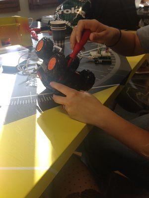
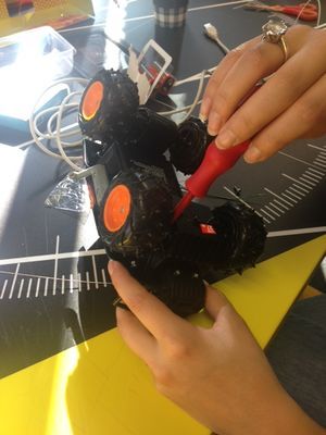
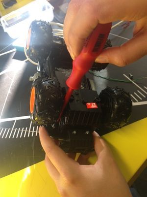
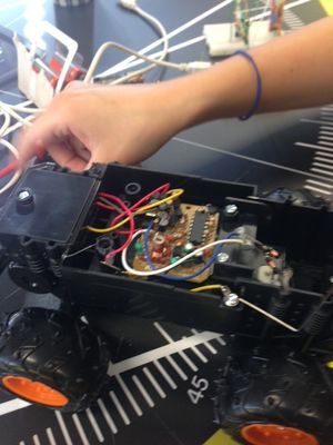
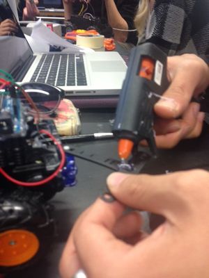
Bonny: buyer all the requisites what we needed to complete our idea, made pictures during the process and sticked the brushes on the car with Thuan Thuan: put the accessories on the arduino Emely: Program the arduino Shus: hacked the controlled toy car and connect it to the arduino(solder)
Concept
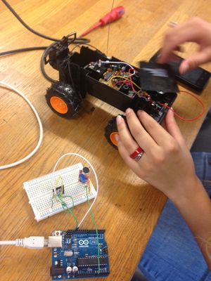
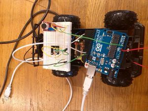
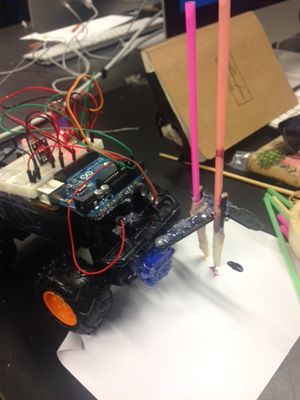
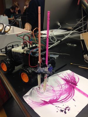
When we had to do this assignment we had no idea what we wanted to create. We started to discuss with the other group what kind of a battle we wanted and then we started with few ideas. Meleny, our fourth member of the group was ill for a long time so we had to do this with three of us in the beginning. We came with the idea to hack an controlled toy and put an arduino in the car so we could control what we wanted. We wanted that the car was reacting on sound and make a move. So we started with hacking the car, than we connect the arduino with the car. From here Meleny was back at the uni and could help us with programing what we wanted on the arduino. The idea was that the arduino was reacting on the sound but we wanted also that we could make drawing with it, so we sticked two brushes on the front of the car, so when the arduino was getting an input the car moved and made an drawing. Drawing on the input.
Techniek
Montage
Hier kunnen foto's en een stukje tekst voor het monteren van de arduino op het autotje, het stukje solderen hoe dat gedaan is uitleggen
Sensoren en Components
Microfoon
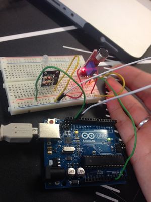
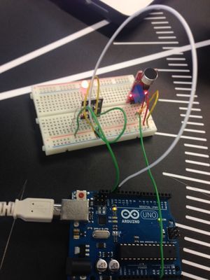
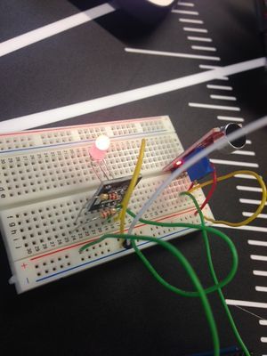
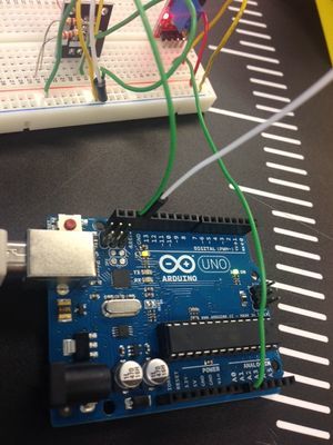
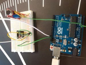
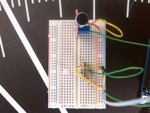
We hebben gebruik gemaakt van een [| Sound Detection Sensor Module] waarvan we in eerste instantie niet precies wisten of deze werkte. Door deze sensor welke bestaat uit een microfoon, een potmeter en een zowel een analoge als een digitale output, los aan te sluiten op de arduino met zowel de digitale als de analoge aansluiting konden we zien welke input er binnen kwam. Door de potmeter bij te stellen kan de gevoeligheid worden afgesteld. Waar we vervolgens achter kwamen is dat de sensor alleen doorgeeft OF er geluid is en niet welke frequentie waardoor er uiteindelijk alleen gewerkt kan worden met het verschil tussen stilte en luide muziek ipv tempo verschillen op een bepaalde frequentie. Met een simpele sensor als deze is dit niet realiseerbaar. Hierbij kan wel worden gedacht aan bijvoorbeeld het volgende systeem: [| Pitch Detection You Tube Filmpje] Maar het nadeel hiervan is dat de arduino niet langer mobiel is omdat deze aan een laptop vastgekoppeld is. Hierom is dit dus geen oplossing.
Servo's
Vervolgens was het de bedoeling dat er 2 servo's aangestuurd zouden worden afhankelijk van de verkregen input uit de microfoon. Eenmaal aangesloten bleek dat de 2e servo teveel stroom trok waardoor de beweging werd vertraagd. Hierom hebben we gekozen om maar 1 servo te gebruiken.
De volgende code is gebruikt om alles aan de praat te krijgen. Op het moment daar kunnen we de potmeter aandraaien zodat het signaal pas wordt doorgegeven bij het juiste geluidsniveau.
Code
/*
  Analog Input
 Demonstrates analog input by reading an analog sensor on analog pin 0 and
 turning on and off a light emitting diode(LED)  connected to digital pin 13.
 The amount of time the LED will be on and off depends on
 the value obtained by analogRead().

 The circuit:
 * Potentiometer attached to analog input 0
 * center pin of the potentiometer to the analog pin
 * one side pin (either one) to ground
 * the other side pin to +5V
 * LED anode (long leg) attached to digital output 13
 * LED cathode (short leg) attached to ground

 * Note: because most Arduinos have a built-in LED attached
 to pin 13 on the board, the LED is optional.


 Created by David Cuartielles
 modified 30 Aug 2011
 By Tom Igoe

 This example code is in the public domain.

 http://arduino.cc/en/Tutorial/AnalogInput

 */
 #include <Servo.h>

int sensorAnalog = A0;    // select the input pin for the potentiometer
    // select the pin for the LED

int sensorDigital = 3;

int servo1Pin = 9;
int servo2Pin  =10;

Servo servo1;  // create servo object to control a servo
Servo servo2;

void moveServo(Servo servo,int stroke)
{
   int servoValue = servo.read();
   if (servoValue == stroke){
    servo.write(0);
     Serial.println("servo to 0");
   }else {
     servo.write(stroke);
     Serial.println("servo to 160");
   }
  Serial.println("moved servo");
 }


void setup() {
  // declare the ledPin as an OUTPUT:
  pinMode(sensorDigital,INPUT);
  pinMode(sensorAnalog,INPUT);
  Serial.begin(9600);
  servo1.attach(servo1Pin);
  servo2.attach(servo2Pin);
  servo1.write(1);
  servo2.write(1);
}


boolean hasMusic =false;
int servoStroke =160;


void loop() {
  // read the value from the sensor:

    hasMusic = digitalRead(sensorDigital);
    Serial.print("has Music: ");
    Serial.println(hasMusic);
    if (hasMusic){
      moveServo(servo1,servoStroke);
      moveServo(servo2,servoStroke);
    }
    Serial.print("Analog: ");
    Serial.print(analogRead(sensorAnalog));
    Serial.print( " Digital: ");
    Serial.println(digitalRead(sensorDigital));
  // turn the ledPin on

    delay(1000);


}
