User:Timo van Dijk
Museum Of Fantastic Forgeries
Wang Guangle - Coffin Paint
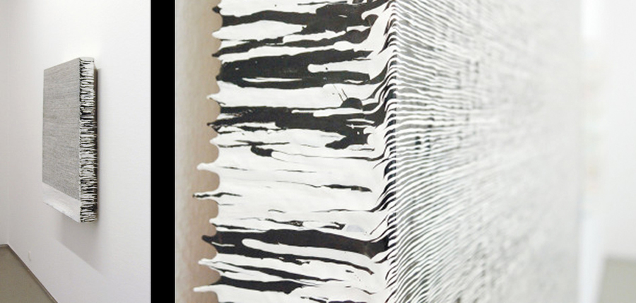
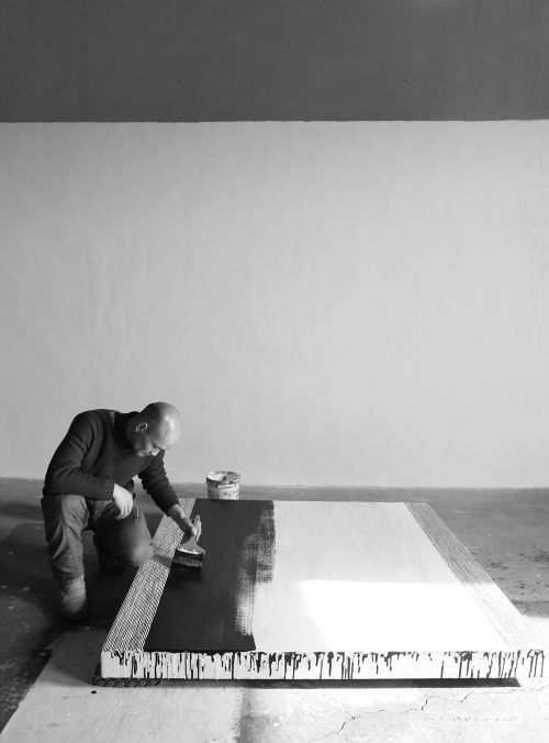
Coffin Paint is a serie of paintings based on the production idea of painting multiple layers of acrylic paint over a period of time. The piece Coffin Paint 131127 (2013) I chose is build out of strokes of white and black paint which Guangle applied two times a day, creating a pattern of thin organic lines. The power behind his series of paintings is the idea and production behind it. It is based on an old Chinese part of culture, in which the Chinese prepare their coffins during their last years.
""...the "Coffin Paints" have a very specific cultural reference: It is customary for some Chinese, as they reach late middle age, to purchase their coffin and repaint it every year, thus hoping to achieve longevity. Wang imagines that his pigment asks to live.""
-mutualart.com 2009 Link-
Guangle used this idea of painting to create different paintings with the same technique.
In a way his way of producing the paintings can be seen as a form of conditional design, where he as an artist restricts himself with a set of conditions on how to produce his work. By applying a layer of white paint, and then wait for half a day for the black layer to build up a whole canvas could be translated as a set of conditions.
Conditional Design
Conditional design is a way of designing work which focusses more on the process instead of the product. The way how the work is evolving or is being created has more importance than the medium. Proces, logic and input are three key aspects of the design. The proces is the product, logic is the tool and input is the material.
Process
For the reconstruction I wanted to use a mechanical way of creating the piece because of the conditional design. A computer works with a design of conditions which are based on logic. The movements of a brush to reporduce the work should be so simple to translate it to conditions for a robot. So I decided to use an Arduino and create a robot who could paint the strokes for the work.
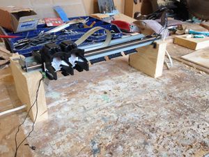
I bought a secondhand printer and took the rail for the printerhead to reconstruct it for the brush to hold and move sideways. The brush only needs to move from right to left and the other way around to paint the work.
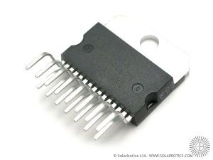
I hoped that there would be a steppermotor inside the printer to get a good control over the brush. But both motors inside were normal DC motors, so I had to find an alternative to use these and let them go into two directions, left and right. For this I needed to use a motor controller that changes the current of the electricity. After a discussion with a salesman in the electronic shop in Amsterdam I found out that all controllers are very specific and hard to fast and for cheap. After some research I found the type of the controller I needed which is a L298 H-bridge. Due to holidays from shop owners and shops that where out of stock I found my controller in Groningen when I happened to be there.
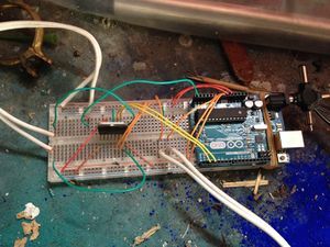
With a breadboard and a Arduino Uno I started to prototype the basic fucntions for the machine. I used the schematics of the L298 to connect the motor and the Arduino in the right way. The L298 has fifteen pins that takes six in- and four outputs. The four outputs can drive two DC motors and the inputs control the direction. A useful aspect of the L298 is that you can connect a seperate power source for the motor so you can put different voltages than the 5V of the arduino and don't have interference in the electric currents between the motor and the Arduino. The Arduino isn't powerfull enough to power itself and the motor simultaniously. So for this setup it's necesary to have a seperate power source for the motor. I used an old AC/DC multi-voltage adapter on which you can choose a voltage between 1,5V and 12V. I measured the motor's current to see on what voltage it performs best for the L298. At 5V it uses on full load of 500mAh. The L298 can handle 600mAh before it burns trhough, so my maximum voltage should be 5V to 6V.
I build two supports from wood for the printer rail and glued the two switches to the sides so the printer head would touch them at the end. For this I wrote a code for the Arduino that if the switch was hit, the motor would go the other way.
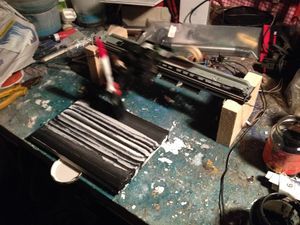
With this I made a test with the same technique as Guangle, painting a stroke, letting it dry and add the second stroke in the other color. I did this for a day, but I was too impatient so the paint mixed some times and became gray strokes. The problem was that the brushes had to be switched every time otherwise they would dry out, and I couldn't automate it that it could switch brushes on its own.
The Arduino code:
int pin2 = 2;
int pin3 = 3;
int switsj1;
int switsj2;
int left = 0;

void setup (){

     pinMode(pin3,OUTPUT);
     pinMode(pin2,OUTPUT);
     pinMode(A0, INPUT);
     pinMode(A5, INPUT);
     Serial.begin(9600);
}

void loop(){
  switsj1 = analogRead(A0);
  switsj2 = analogRead(A5);

  if(switsj1 >= 1021){
    left = 1;
  }else if(switsj2 >= 1021){
    left = 0;
  }

  if(left == 1){
    digitalWrite(pin2,HIGH);
    digitalWrite(pin3,LOW);
  }else{
    digitalWrite(pin3,HIGH);
    digitalWrite(pin2,LOW);
  }

  delay(100);
}
