User:JeroenRijnart/HTBHQ13
Contents
Project 1: On The Body
Teammate: Tim Reuser
Concept
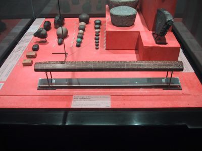
Our team had the thumb, hand and arm as body parts. Through history these body parts have been used as units of measurement. Firstly we wanted to communicate this fact somehow.
Cubit rod in the Museo Egizio of Turin, showing digit, palm, hand and fist lengths.
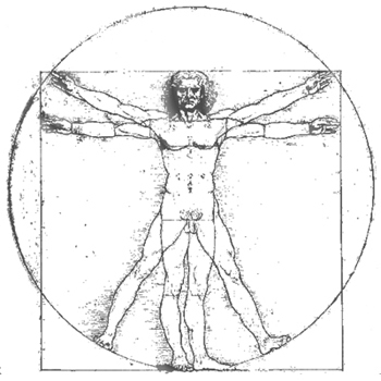
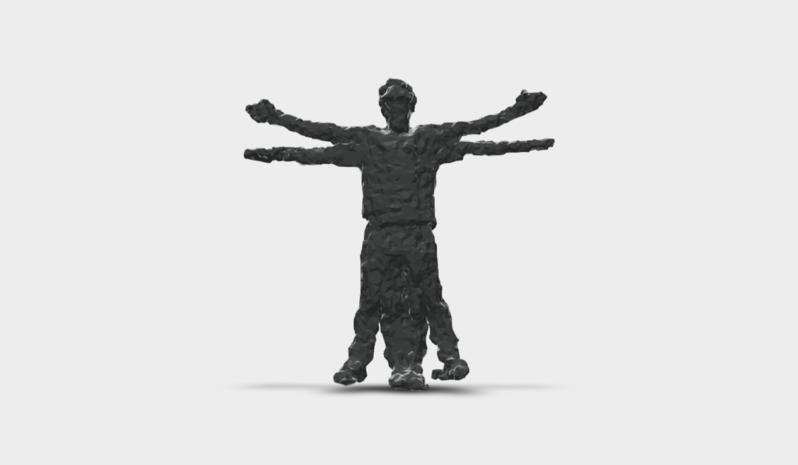
We then turned it around to measuring the body, Da Vinci's vitruvian man standardized body measurements using the golden ratio. This is however, of course, completely unrealistic. This was the idea we wanted to communicate now.
Attempt 1: Stretchy cubit (ruler)
The first idea was a rubber cubit rod. Cubits as a unit of measurement varied significantly throughout time and location, a stretchable cubit rod was to communicate this fact. We quickly decided this wasn't interesting enough and abandoned this course for other ideas.
Attempt 2: Measuring bodies
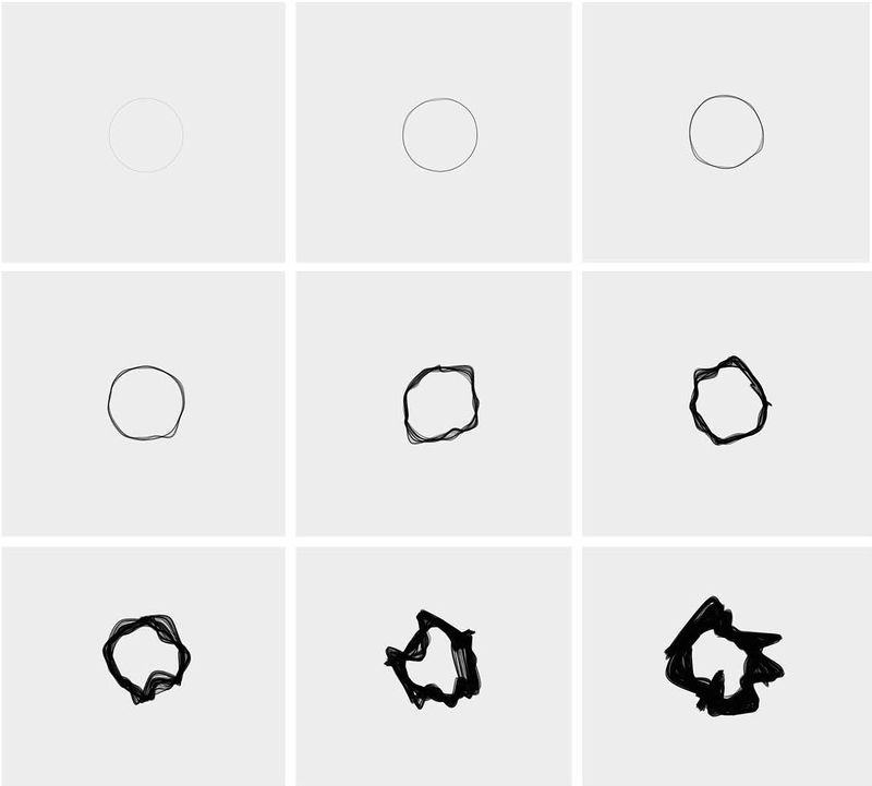
Then we moved on to the scanning and measuring of bodies. We wanted to make a publication with these body scans and have some graphically exciting way to show our data. There was no real concept behind it, just the act of measuring. The publication however, was never made. We abandoned this course for other ideas.
An abstract way to show our data.
Result
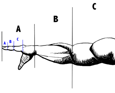
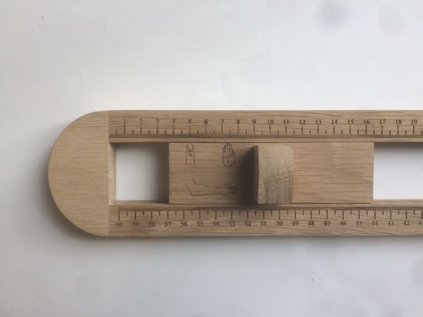
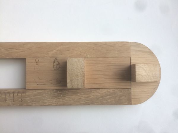
Finally we went for a reversed cubit rod, a tool to measure your finger segment, palm span and arm length.
Project 2: Inhuman Factors / Sensitivity Training
Teammate: Jochem Walboomers / Suzanne Guitjens
Concept
For the kick off of this project I made a hall sensor, a sensor for detecting magnetism. We ended up going with Jochems light sensor.
Attempt 1: Mouse scanner
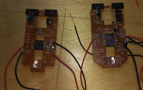
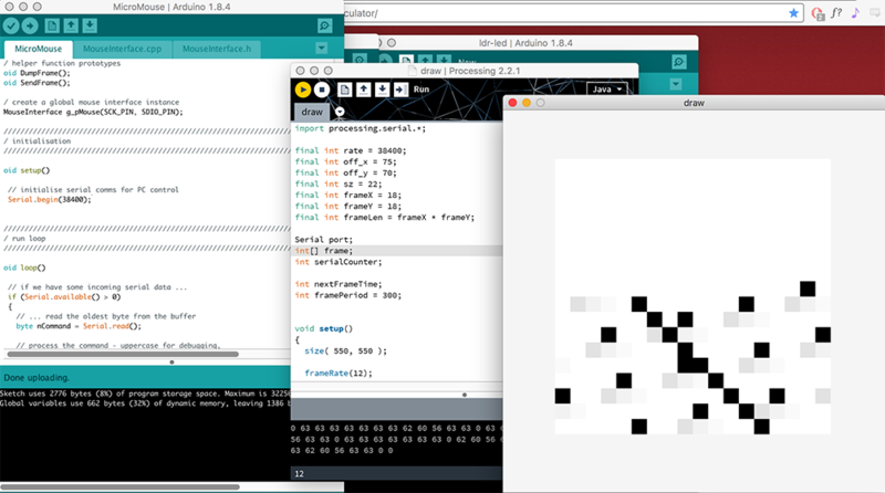
We wanted to hack a mouse into a low res hand scanner, optical mice use sensor chips that are essentially super tiny camera's. We opened up a lot of computer mice and looked up the data sheets of the specific chips they used. We needed to solder wires to the ground, power, data clock and data i/o pins.
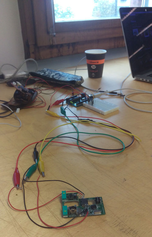
The mouse that showed the most promise worked on a lower voltage than 5v, so we made a voltage regulator for in between the mouse and the arduino.
We used an arduino and processing to try to draw a sixteen by sixteen grid in greyscale. Unfortunately we only received junk data, it became apparent that if we would continue this course we would not have a working project or satisfactory end result by the end of the project.
Attempt 2: Webcam microscope
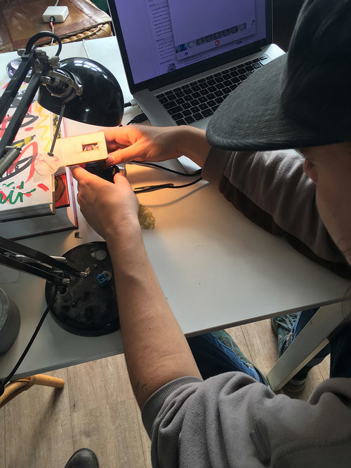
In the second week we decided to modify a webcam into a microscope.
My sweaty hand.
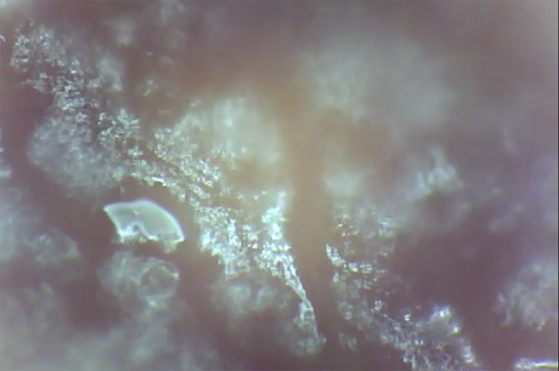
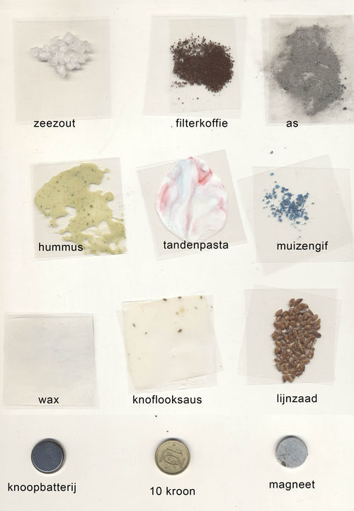
We started filming different materials, from the top and bottom. We shone light through translucent materials or on it if they were solid. We played around with the angle and colours of the light. For instance, by moving light across a LP record we could see the shadows of the grooves shift.
Some of the materials we used.
In the end we made an abstract film for which we also made the music. A microscopic music video. In the back you can see the webcam on the table along with different materials/stuff we used.
Result
>>>>>>>>>>>>>Microscopic film<<<<<<<<<<<<<
Project 3: Mind (of) the Machine
Teammate: Alex Laman
Concept
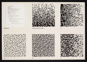
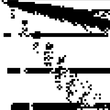
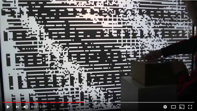
For this project we wanted to make a machine mind for which the user would make the connections between the different chambers of the brain. The visual output is based on Peter Struyckens Computer Structures.
The hardware
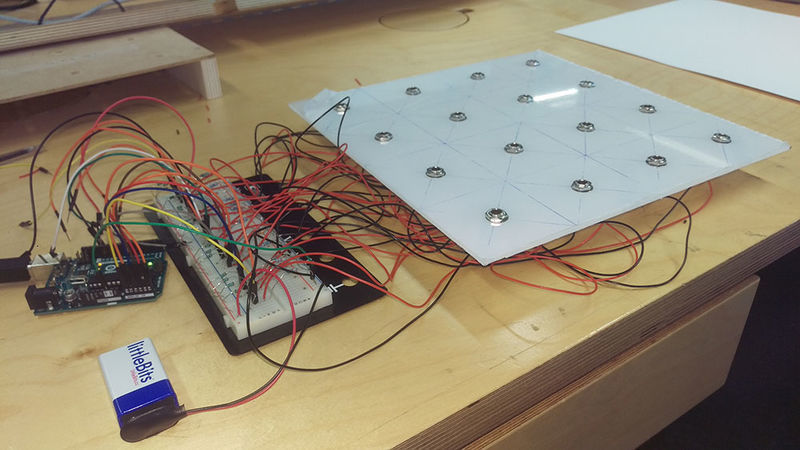
The idea was that by making voltage dividers for every input plug we would be able to identify which input plugs are connected on the arduino.
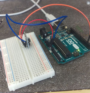
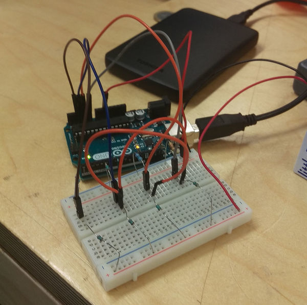
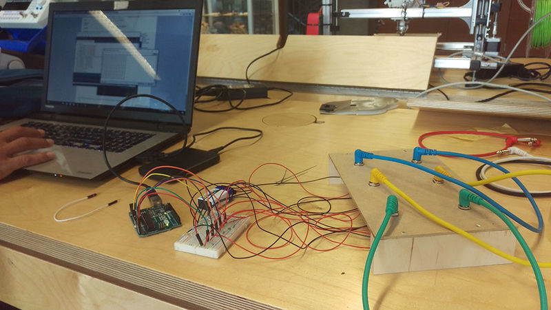
Below you see the first prototype on a breadboard with some voltage dividers, here we found that when you connect two of the circuits the resistance (or rather, the voltage) of these two would become the same. This is how we tell the arduino that two plugs are connected.
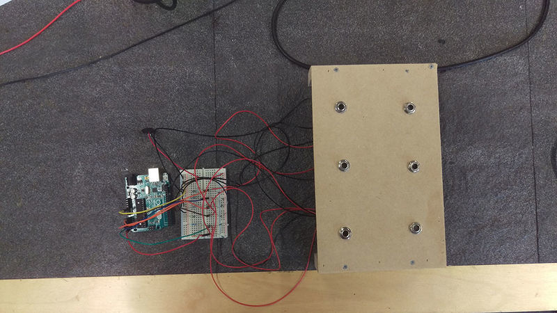
Then we made a panel with jack inputs and connected it to the breadboard to see if this would still hold up.
We can see on the computer that when no cables are connected we get six different numbers, as soon as we make a connection the numbers of the corresponding jack inputs become the same.
Then we made the top panel for the box from semi transparent perspex, we expanded to sixteen voltage dividers, using different resistors for every input.
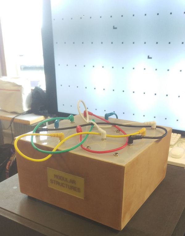
The finished box with title and short legs under it.
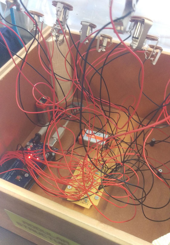
We made a system with magnets to seal the top panel to the box, we soldered the circuit and mounted everything in the box. You can shake the box or hold it upside down and it won't break. We wanted to make it as durable as possible.
The software
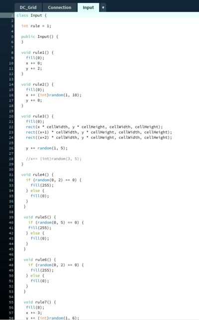
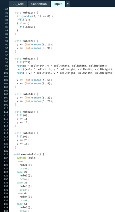
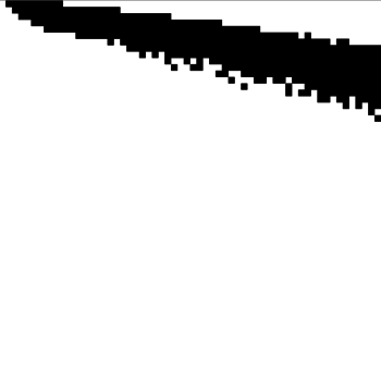
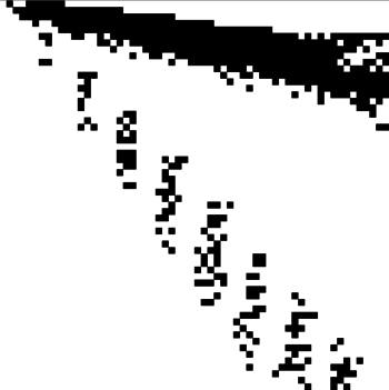
There are two programs at work, code on the arduino that sends the numerical values associated with the jack plugs to an external computer, and software made in processing that uses this data. The processing code is built up in "rules". Every jack input has its own set of rules on where to draw squares, by combining two jack inputs these rules will work together to make an image.
Here you see how the rules are structured
testing some connections on the computer
From left to right: one connection, two connections, three, four.
Result
>>>>>>>>>>>>> Modular Structures <<<<<<<<<<<<<
The face of things: MICA meets digital craft
Concept
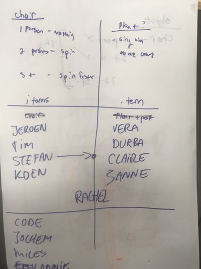
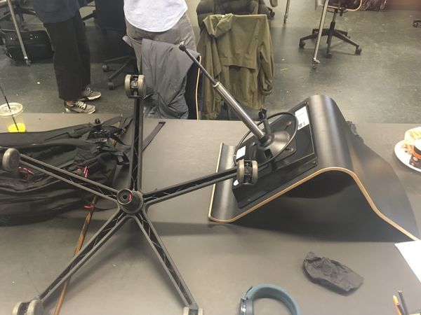
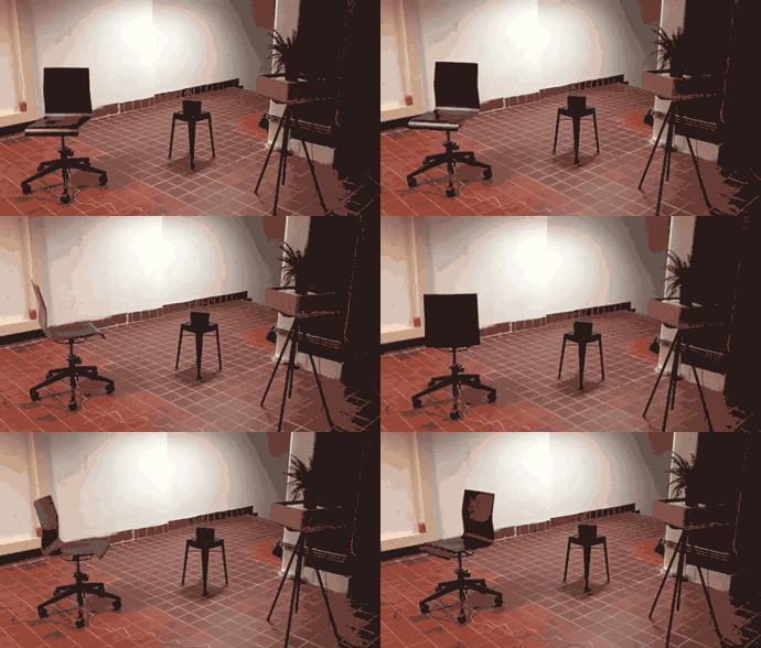
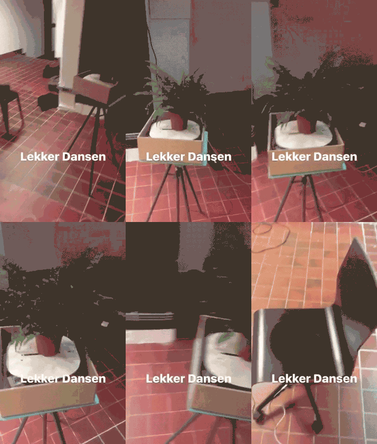
I was in team anthropomaterials, on tuesday we started discussing how we could bring an object to life. It was hard reaching a consensus in such a huge group, but on wednesday morning we decided to make two anthropomorphized objects so we could split the group in three. We chose a plant and a chair, and the concept became a "living" room. The objects would move based on their inherit traits, and their personality would be shy. The final result would be a dancing plant and chair with a radio, only they would stop dancing when someone would enter the room. One group would work on the chair, one group would work on the plant and one group would work on the webcam that would detect people in the room.
Process (dancing chair)
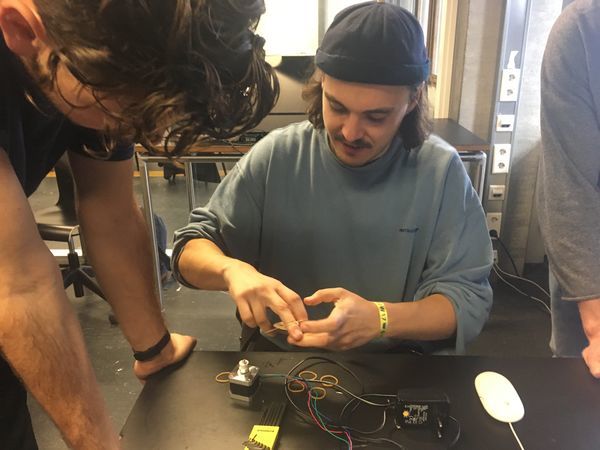
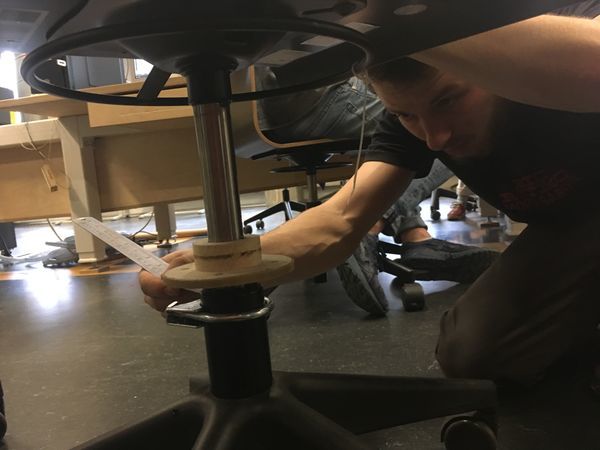
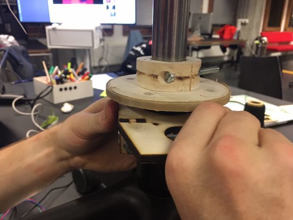
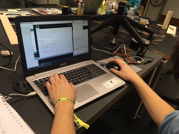
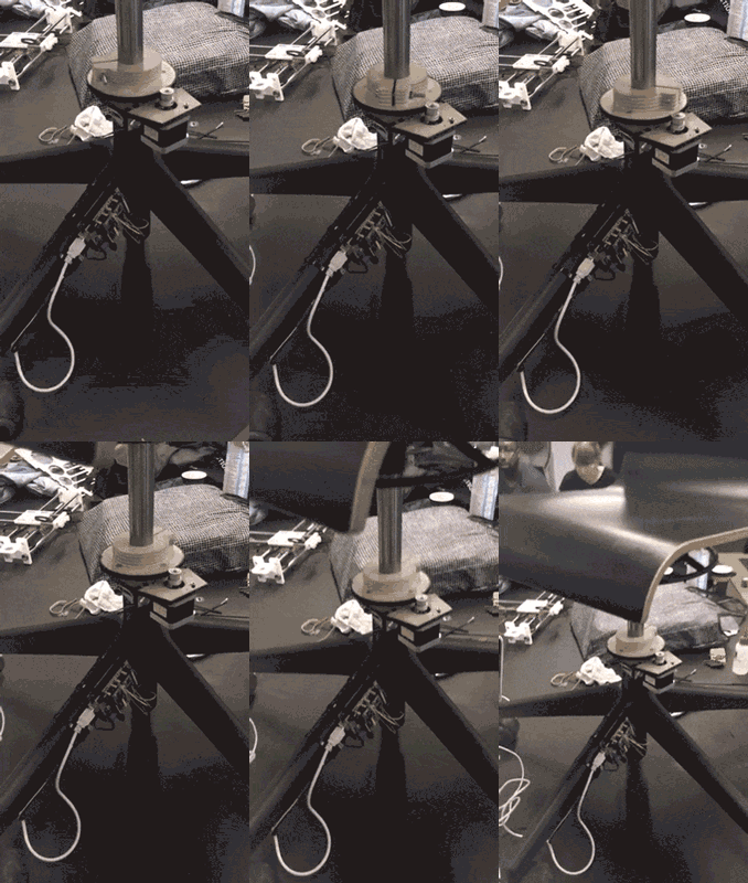
We used a step motor, an arduino and a step motor shield to power the swivel mechanism. The step motor was placed against a wooden ring and used friction to make the chair spin. This way it would have a more natural sway.
The finished mechanism:
The documentation of the whole team can be found here: http://digitalcraft.wdka.nl/wiki/Utc2017#Anthropomaterials
Result
The dancing living room:
The objects turn shy when you stand close to them:
My craft
Even though I study graphic design I do not consider myself a real graphic designer. I am not interested in designing house styles, logo’s or business cards. I hardly work with print, I have made very few books and I’m not particularly adept at typography. As of yet I haven’t been able to commercially apply myself and I loathe having to execute someone else’s ideas. I don’t care if users or viewers have a hard time comprehending or interacting with my work. I do consider interaction or user experience to be very important, but this doesn’t necessarily has to be easy or obvious as it would be in any commercial product or service. I am keen on aesthetics and I love powerful experiences. Even though I enjoy working autonomously, I don’t consider myself an artist.
For some time now I have been interested in generative design. In my second year of the Willem de Kooning academy, and my first quarter following the digital craft practice, I did a project called ‘digital input control’, which was an installation with which users could create abstract posters using a modified analog video processor. In believe that in this project, the user and I shared authorship in the created works. Since then I have worked on several projects where I have designed systems that either autonomously or by user input generate image and sometimes sound. That’s why I consider myself a designer, that being said, I am interested mostly in the grey area between art and design.
I view “new” technology as a way to explore new concepts and expression, they say that in art everything has been done before but with new technology comes new possibilities. It is true that nothing is created in a void and everything has a historical context, but I do believe that with new technology new fields to explore artistically emerge. Technology is everywhere an can be appropriated, discarded machines can be given new life in new contexts. And of course, this being the information age, it would be a waste to not use all information available. Learning about new skills, tech or techniques can be only a mouse click away. But still I learn by doing, when I make something I try to craft it as well as I can, and my craft has to be honed always. I try to achieve this by challenging myself and trying new things in every project. The technology I use must make sense within the concept, and concepts change as technology is explored. This makes for an intuitive process, that I try to execute methodically.
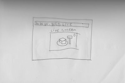
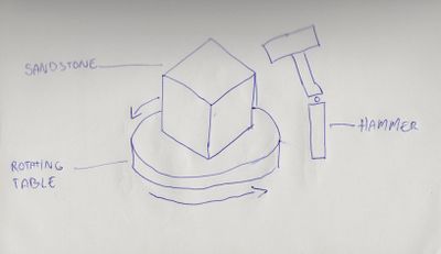
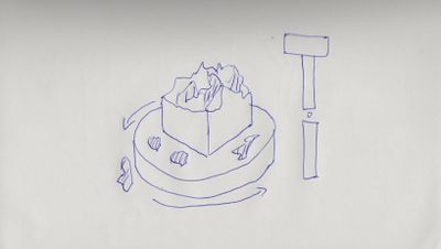
In quarter 14 I am going to work together with Jochem, and we’re going to explore the themes of co-authorship on the web, the boundaries between virtual and physical space and the (increasing/ decreasing) significance of objects when shared online. The project will be accessible for everyone with an internet connection, but the physical object will only be at one specific location.
