Difference between revisions of "User:AlessandraStradiotto"
| Line 4: | Line 4: | ||
[[File:Ale.JPG|thumb]] | [[File:Ale.JPG|thumb]] | ||
I'm Alessandra Stradiotto, a Graphic design student from Brazil! Welcome to my page! | I'm Alessandra Stradiotto, a Graphic design student from Brazil! Welcome to my page! | ||
| + | <br /> | ||
| + | <br /> | ||
E-mail: alessandra_psp1@hotmail.com | E-mail: alessandra_psp1@hotmail.com | ||
| − | |||
| − | |||
| − | |||
| − | |||
| − | |||
| − | |||
| − | |||
| − | |||
=Assignment 1: I Draw. You Draw. It Draws= | =Assignment 1: I Draw. You Draw. It Draws= | ||
Revision as of 09:35, 15 June 2016
Mimicking Machines 2016
Contents
Nice to meet you!
I'm Alessandra Stradiotto, a Graphic design student from Brazil! Welcome to my page!
E-mail: alessandra_psp1@hotmail.com
Assignment 1: I Draw. You Draw. It Draws
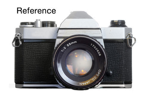
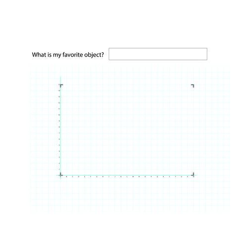
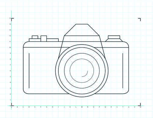
The machine that I chose is a photo camera. I google it to get an image as reference and then I drew the vector in Illustrator. In the instructions, I chose to set all the variables such as the table space that the person needs and the material. Based on coordinates, I simplify the drawing to be possible to be executed.
Instructions
1. Find a table with free area of at least 600x900mm;
2. Take a seat;
3. Take a 1mm pencil or pen;
4. We are going to start drawing the grid. If you already have the proper grid, please go to step 15.
5. Start drawing one horizontal line in the middle of the left lower quadrant of the page. The line should be 400mm long;
6. Taking into consideration the line you have already drew, measure 16mm distance;
7. Measure 16mm upward and draw a parallel horizontal line;
8. Repeat steps 6 and 7 fourteen more times;
9. To draw the vertical lines of you grid, go to the point (0,0) of you lowest line (the first line you drew);
10. Draw a 280mm perpendicular line;
11. Assuming you first horizontal line is the X axis, measure 16mm in this axis to its right;
12. Draw another vertical line;
13. Repeat the steps 11 and 12 twenty one more times;
14. Give names to each line following this rule: the horizontal lines are named with letters in the alphabetical order (a, b, c, d, e, f, g, h, i, j, k, l, m, n, o, p, q, r, s, t, u, v, w) and the vertical lines are named with numbers starting with 0 (0, 1, 2, 3, 4, 5, 6, 7, 8, 9, 10, 11, 12, 13, 14, 15);
15. Now you have the grid, let us start drawing our machine;
16. Find the cordinate C3;
17. Draw a line from C3 to C10;
18. Draw a line from C10 to K10;
19. Draw a line from O10 to U10;
20. Draw a line from U10 to U3;
21. Starting from U3 and finishing at T2, draw a ¼ circunference arc of radious 17mm;
22. Draw a line fromT2 to O2;
23. Draw a line from K2 to D2;
24. Starting from D2 and finishing at C3, draw a ¼ circunference arc of radious 17mm;
25. Draw a line from D3 to D9;
26. Draw a line from T3 to T9;
27. To draw a circunference, find the cordinate M6. Assume that this is the center of the circunferences the four next circunferences that follows;
28. Draw a circunference with 32mm radius;
29. Draw a circunference with 48mm radious;
30. Draw a circunference with 64mm radious;
31. Draw a circunference with 72mm radious (this one will be in between the coordinates H and I);
32. Draw an ¼ circunference arc starting from N6 and finishing at M5. Take into consideration the center of this circunference also M6;
33. Draw a diagonal line from I8 to J12;
34. Draw a line from J12 to P12;
35. Draw a diagonal line from P12 to Q8;
36. Draw a diagonal line from J12 to L14;
37. Draw a line from L14 to M14;
38. Draw a diagonal line from N14 to P12;
39. Considering the center of the circunference at D10, draw a circunference arc from C10 to D11;
40. Draw a line from D11 to T11;
41. Considering the center of the circunference at T11, draw a circunference arc from T11 to U10;
42. Draw a complementary line between 11 and 12 in you Y axis. Call it 11.5. Make sure you can erase this line after finishing your draw;
43. Draw a line from D11 to D11.5;
44. Draw a line drom D11.5 to F11.5;
45. Draw a line from F11 to F12;
46. Draw a line from F12 to G12;
47. Draw a line from G11.5 to I11.5;
48. Draw a line from I11.5 to I11;
49. Draw a complementary line between D and E in your X axis;. Call it D1;
50. Draw a complementary line between E and F in your X axis. Call it E1;
51. Draw a line from (D1;11.5) to (D1,12);
52. Draw a line from (D1,12) to (E1,12);
53. Draw a line from (E1,12) to (E1,11.5);
54. Draw a diagonal line from Q11 to the middle of the square/cell;
55. Draw a complementary line between Q and R (Q1) and S and T (S1);
56. Draw a line between (Q1, 11.5) to (S1, 11.5);
57. Draw a diagonal line between (S1, 11.5) to (T11);
58. Draw a line from (Q1, 11.5) to (Q1, 12);
59. Draw a line from (Q1, 12) to (S1, 12);
60. Draw a line from (S1, 12) to S1, 11.5);
61. Erase all the complementary lines;
62. Say “I am done”!;
63. Figure out what is my favorite machine;
Assignment 2: The Extruded Milled and Sliced Alphabet
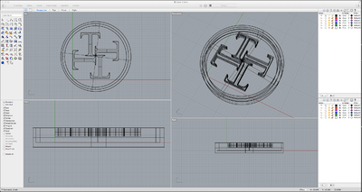
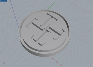
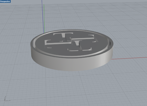
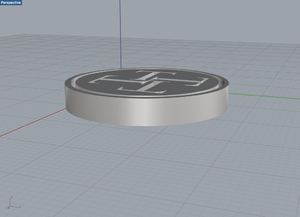
I got the letter "T" to design a simple 3D model.
Sketching the idea
Process
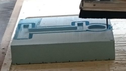
In the software Rhinoceros, I designed my model considering that it would be fine to print it in the melling machine. When I went to to Digital Lab to print it, I talked with the instructor and he advised me to laser cut it instead of milling it. I hadn't considered this possibility so far, but when he explained me it did look faster and more accurate. As I had both file, the stl (3d file exported from Rhino) and the ai (illustrator format), it was easy to convert my letter/object into layers. The material I chose to use 6mm MDF, that I bought in the Wood Station at WdKA.
Reflection
When I designed my file, I was already aware that I could not have sharped corners if I would use the melling machine. However, I thought that it could be a slight difference between my model and my printed version. When I figured out that I could use the laser cutting machine, I knew that I would have much more control over my final file in this case, since it allows me to precisely cut some pieces. In the beginning of the course it was quite abstract to take into consideration all the limitations of each format since I had never used it before. However, as soon as I did this assignment it helped me to understand both mechanisms and I know I feel a bit more familiarized with it.
The technology - laser cutting machine
I used the laser cutting machine to build my 3D model. To do so, I sliced my object in two parts. As the name of the machine suggests, it cut my piece of wood (the material that I chose) really precisely. The machine works with different materials: paper, wood and, in some cases, some kinds of metals. The machine was faster than the milling machine and the 3D printer, so it was the best option to print my model.
Example in class
Assignment 3: Human Powered Machine
The concept
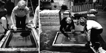
Andy Warhol was a leading figure of the Pop Art movement. In terms of technique, Warhol introduced the serigraphy in the art world as a mechanical way of reproducing his images. The silkscreens, reproduced serially, depicts objects of our everyday life, a translation of the capitalist world of brands, celebrities and icons. At that time, the technique has already changed the way the deal with art and virtuosity. What does it mean to a art piece to be reproduced endless times? In the opposite direction, never before have we used so many times the word “exclusive”.
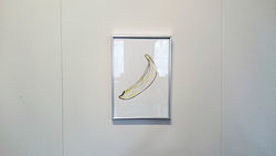
In the project that I like to call “Warhol 2.0” brings this thought to another level. By using the milling machine, I reproduced two works of Andy Warhol with watercolour ink. Once you have the file with your art, the machine become the real executor of this work. The “hands of the painter” no longer exists.
After producing the drawings, they were framed in the attempt of faking the “aura” of an artwork, based on the ideas of Walter Benjamin.
The process
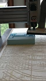
The project was developed for the final assignment of Mimicking machines at Willem de Kooning Academy. Considering the classes we had, I thought about changing a bit the relation machine-human. Instead of designing a new machine based on human behaviour and abilities, I chose to do the opposite. What if a machine can reproduce what we value most, our art…? In this way, the machine would become a mechanical arm that is able to mechanically reproduce anything.
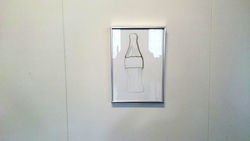
In order to do so, I first looked at Andy Warhol’s artworks and selected two of them to reread it. I chose “The Velvet underground and Nico cover” and the “Coca Cola” to work with.
After that, I drew in vectors that I want to test. Having the Illustrator files, I went to the Digital Lab at WdKA to execute it.
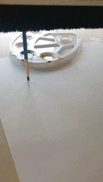
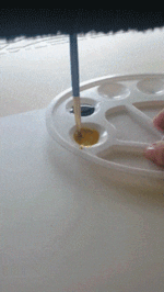
At that moment, I had to think how to make the brush take the ink from the palette. To solve that, we set one specific spot that the ink would be placed and the machine could go there and follow random lines to take the ink. As the drawings were not super complex, it went well. If the drawing were more complex, I would have to set the machine to come back and refill ink.
Please access the full video at [Milling machine process - painting with watercolour]
Material
- Brush;
- Watercolour (yellow and black);
- Canson paper - A3 size;
- Palette;
- Milling machine;
- Vector software (in my case, Adobe Illustrator)
Design
The files had different layers. Each layer is related to one step of the drawing, in my case, it was related with the amount of colours that I was going to work with. All the drawing are digitally made in a vector software, in my case, Adobe Illustrator. I also did a test to see how a typography works. Due to the lack of ink in the last letter, the word fades gradually.
Download the files
Feel free to download all the files and play with it: [Editable files desgn+3d]
The results
It was the first time that I used the milling machine and the results with the ink were quite impressive. The accuracy of my drawings were high and the project worked really well. However, the machine did not work independently of human help. The only part that I had to touch in the machine was to hold the palette. If I did not do so, the bush would push the palette. It could be easily solved, I would just need to hold it to the table. The Digital Lab instructor was also really surprised with the results and the asked me to keep the files since it would be something nice to show in an Open Day. Since the machine can be really noisy, they usually demonstrates it with a marker. However, nobody has tried to do something with ink. I was really pleasant to see it working and to be able to recognise the potentialities of the machine.
Reflection
I was personally really interested in this project since I have never tried it before. I did not except the result to be as accurate as it ended up being. It was a great surprise and it gives me some ideas of really challenging drawings that I could test by using this kind of mechanical reproduction. One possibility that I could have tested was to work with different depths in the same drawing. The first thing I drew, I considered to work with one colour only. But then I tested with more colours and it helped me to understand the software and the machine, since it has the “profiles” and it follows a logical order that we could play with. I hope I can further explore these tests back home and I also hope that the Digital Lab could also show it to more students as another possibility.
